Metal hard sealing butterfly valve with moving valve seat

A mobile, hard-sealing technology, applied in the direction of lift valve, valve details, valve device, etc., can solve the problems of valve plate sealing ring and valve seat stuck, valve plate easily stuck, high cost of manufacturing materials, to ensure two-way The effect of sealing performance, simple processing technology and simple manufacturing process

Inactive Publication Date: 2015-08-26
LIUZHOU IRON & STEEL
View PDF12 Cites 9 Cited by
  • Summary
  • Abstract
  • Description
  • Claims
  • Application Information

AI Technical Summary

Problems solved by technology

The sealing pair of metal hard-sealed butterfly valve with eccentric structure is a non-positive cone rotating surface, which requires high processing equipment configuration and processing technology control. The sealing pair needs to be paired and processed, with poor interchangeability and high manufacturing process costs.
[0004] 2. Strict requirements for sealing materials
Considering factors such as temperature changes, fluid scouring, and blind plate force of metal hard-sealed butterfly valves in use, it is necessary to ensure the reliability of the non-positive cone rotating curved surface sealing pair, which requires high performance of the sealing pair material and high manufacturing material costs.
[0005] 3. Poor sealing reliability
[0006] 4. The valve plate is easy to jam
In order to achieve the sealing performance of the metal hard seal butterfly valve, proper extrusion and deformation between the sealing pairs are required. When the medium in the flow channel is in the forward flow state, the higher the medium pressure, the tighter the sealing extrusion will be, which will easily cause the sealing ring of the valve plate and the valve seat to be stuck. dead, causing the valve to fail to move

Method used


Image

  • Metal hard sealing butterfly valve with moving valve seat
  • Metal hard sealing butterfly valve with moving valve seat
  • Metal hard sealing butterfly valve with moving valve seat

Examples


Embodiment Construction

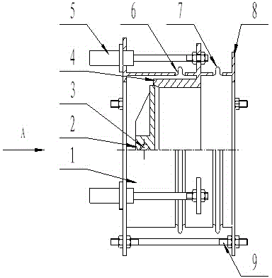
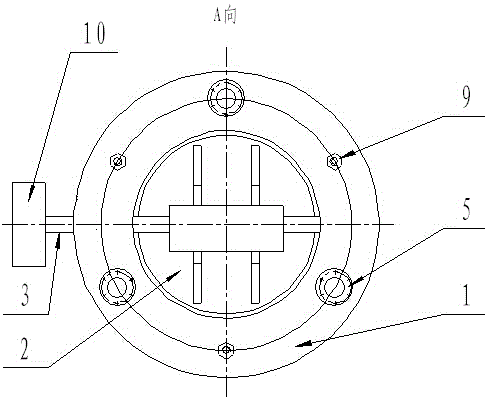
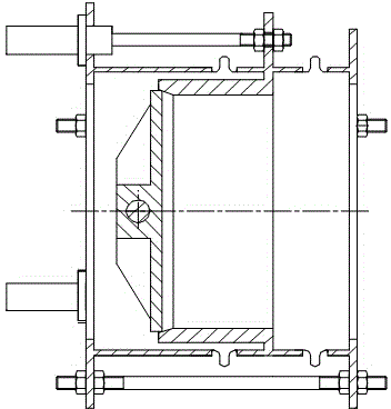
[0026] Such as figure 1 , 2 As shown, this embodiment includes a valve body 1, a valve plate 2, a valve shaft 3, a circular sealing valve seat 4 and a valve plate driving device 10, the valve plate 2 is fixed on the valve shaft 3, and under the action of the valve plate driving device 10, the valve The rotation of the shaft 3 can realize the movement of the switch rotation. The valve plate 2 and the circular sealing valve seat 4 form a spherical or conical metal hard sealing pair. There is a valve body shoulder at the corresponding position, and the valve seat driving device 5 is an oil cylinder, and its two ends are respectively connected with the installation shoulder of the circular sealing valve seat 4 and the valve body shoulder of the valve body 1, and the valve seat driving device 5 The driving effect of the driving action drives the circular sealing valve seat 4 to move left and right along the axis of the valve body, which can realize the compression and separation b...


PUM


Abstract

Provided is a metal hard sealing butterfly valve with a moving valve seat. A first metal expansion joint is connected between the front end of the round sealing valve base and a valve body, a second metal expansion joint is connected between the rear end of the round sealing valve base and a valve body flange, and a valve seat driving device is connected between the round sealing valve seat and the valve body and drives the round sealing valve seat to move left and right along the axis of the valve body. When the valve is in the closed state, the round sealing valve seat moves to the position where the round sealing valve seat is connected with a valve plate in a sealing mode, and when the valve is in the open state, the round sealing valve seat moves to the position where the round sealing valve seat is separated from the valve plate. The metal hard sealing butterfly valve has the advantages that the two-way pressure bearing and sealing performance is achieved, and the effect of the valve seat driving device can guarantee the sealing specific pressure of a sealing pair; the spherical surface or regular conical surface metal hard sealing pair is adopted for the valve plate and the valve seat, the machining process is simple, the sealing pair can achieve surface contact easily, and the interchangeability of the sealing structure is good; the sealing valve seat is of a horizontal moving structure, and therefore the opening or closing movement is reliable.

Description

technical field [0001] The invention relates to a metal hard seal butterfly valve used in the manufacture of metal hard seal butterfly valves and fluid pipelines, in particular to a metal hard seal butterfly valve with a movable valve seat. Background technique [0002] The metal hard seal butterfly valve is widely used in the on-off of pipeline fluid because of its simple structure, relatively small opening and closing torque, and convenient use. In order to improve the working pressure of the metal hard seal butterfly valve and ensure the flexible and reliable opening and closing performance, the existing metal hard seal butterfly valve, because its valve body and sealing valve seat are both fixed structures, to realize the rotation and sealing of the valve plate, there are many structural forms. The triple eccentric structure is adopted, and the sealing pair between the valve plate and the sealing valve seat adopts a rotating curved surface, which has the following defic...

Claims


Application Information

Patent Timeline
Patent Type & Authority Applications(China)
IPC IPC(8): F16K1/228F16K1/226F16K1/36F16K1/38F16K27/02
CPCF16K1/228F16K1/226F16K1/36F16K1/38F16K27/0218
Inventor 赵泽文黄庆周张洪波谢庆生蒙志明杨华门友华刘风伟唐定忠杨海廷李文松曾闯阮第辉黄能钰李大明
Owner LIUZHOU IRON & STEEL
Why Eureka
Try Eureka