
High soft membrane flexible coupler

A diaphragm coupling, flexible diaphragm technology, applied in elastic couplings, couplings, mechanical equipment, etc. Service life and other issues, to solve the problem of axial position locking, eliminate curvature interference, and improve flexibility

Inactive Publication Date: 2009-12-09
SUZHOU FL COUPLING DRIVE ENG
View PDF0 Cites 6 Cited by
  • Summary
  • Abstract
  • Description
  • Claims
  • Application Information

AI Technical Summary

Problems solved by technology

However, although the thickness of the diaphragm of the coupling is very thin, it still has a certain thickness. Therefore, when the laminated diaphragm is bent for angular displacement compensation, due to the difference in curvature between the inner and outer surfaces, there is a gap between adjacent contact diaphragms. Curvature interference, curvature interference causes high-frequency wear and contact fatigue between the diaphragm contact surfaces, and severe wear will lead to premature failure of the coupling diaphragm
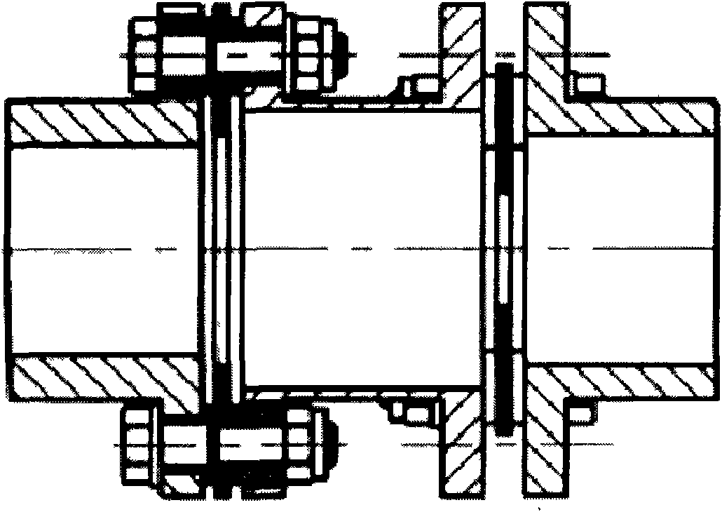
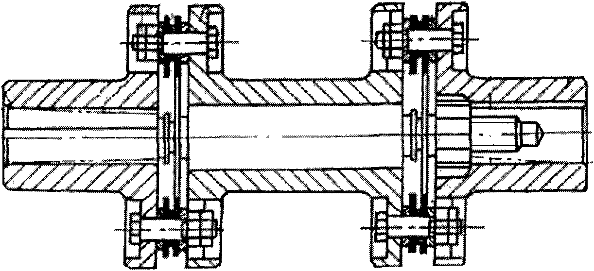
[0008] 3. The traditional annular diaphragm flexible coupling ( figure 1 ) and JB / T9147-1999 lap rod diaphragm coupling ( figure 2 ) The flexibility (softness) that provides three items of misalignment displacement compensation for the equipment all comes from the bending deformation of the diaphragm. When the design is improper and the lamination of the diaphragm is too thick, the bending resistance of the lap rod diaphragm coupling The section coefficient may be several times or even ten times that of the annular diaphragm flexible coupling, so that the internal stress of the diaphragm group becomes very large when it is bent and deformed
However, limited to the conditions of the equipment installation site, most companies do not follow the provisions of the coupling installation manual when installing the coupling, but use copper rods, aluminum rods or even steel hammers to directly hammer the flange of the coupling method of forcing the coupling into place brutally
The serious consequence of such an installation method is to cause permanent deformation of the coupling components, seriously destroying the mechanical properties of the coupling, thereby reducing the service life of the equipment

Method used


Image

  • High soft membrane flexible coupler
  • High soft membrane flexible coupler
  • High soft membrane flexible coupler

Examples


Embodiment

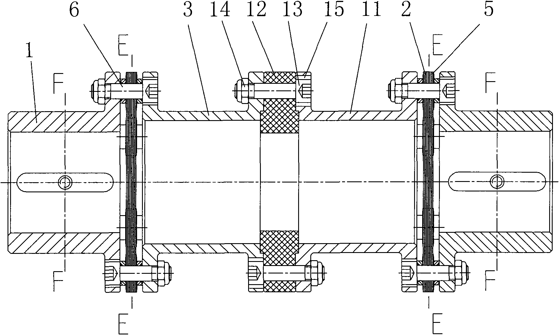
[0029] Example: such as Figure 3 to Figure 5 As shown, a high-flexibility diaphragm flexible coupling includes flanges 1 at both ends and at least one diaphragm ring 2. When there are more than two diaphragm rings 2, the two diaphragm rings 2 are connected There are spacer disks or spacer shafts 3, and the diaphragm ring 2 of the coupling is composed of more than two pairs of 8-shaped laminated diaphragm rods 4 with openings at both ends. In the opposite openings of two adjacent staggered laminated diaphragm rods 4, riveted bushes and spherical washers are riveted to form an end-to-end diaphragm rod ring chain 5, and several bolts 6 pass through the openings respectively, and the above-mentioned diaphragm The sheet rod chain 5 is fixed on the flange 1 or the spacer disc and the spacer shaft 3 at both ends. The utility model uses the diaphragm rod chain 5 to replace the traditional annular diaphragm chain made of the whole high-quality material and the tower connecting rod di...


PUM


Abstract

The invention discloses a high soft membrane flexible coupler, which comprises flanges at two ends and at least one membrane ring. When the high soft membrane flexible coupler is provided with more than two membrane rings, a spacing disc or a spacing shaft is connected between two membrane rings; the membrane rings of the coupler are connected by more than two pairs of 8-shaped lamination membrane rods which are provided with open pores at two ends and align open pores at two ends at intervals one by one to form a membrane rod ring chain end to end; and a plurality of bolts pass through the open pores respectively to fix the membrane rod ring chain on the flanges at two ends or the spacing disc or the spacing shaft. The high soft membrane flexible coupler can greatly improve the softness, flexibility, displacement compensation ability and economy of the membrane coupler.

Description

technical field [0001] The utility model relates to a high flexibility diaphragm flexible shaft coupling. Background technique [0002] The flexible coupling is a mechanical concept product full of contradictions, and it has two missions that cannot be neglected: ① transmit the torque of the prime mover to the driven machine safely, reliably and quietly; ② due to the inevitable In the presence of manufacturing errors, installation errors, and factors such as load-bearing deformation and thermal deformation of equipment under dynamic conditions, there must be three misalignment displacements in the axial, angular, and radial directions between the axes of the prime mover shaft and the driven machine shaft Deviation, another important mission of the flexible coupling is to use the softness of its own elastic elements to make reconciliation, concession, deformation and compensation for the three misalignment displacement deviations of the equipment, collectively referred to as:...

Claims


Application Information

Patent Timeline
IPC IPC(8): F16D3/56
Inventor 黄天梵丁邦建
Owner SUZHOU FL COUPLING DRIVE ENG
Learn More