Supercharge Your Innovation With Domain-Expert AI Agents!

PC card controller with reduced number of terminals

A technology of computer systems and subsystems, applied in measuring devices, instruments, electrical digital data processing, etc., can solve problems such as difficulties in finding locations for special function terminals

Inactive Publication Date: 2007-12-12
O2 MICRO INT LTD
View PDF9 Cites 0 Cited by
  • Summary
  • Abstract
  • Description
  • Claims
  • Application Information

AI Technical Summary

Problems solved by technology

However, manufacturers of PC card controllers are continually removing reserved and unused terminal functions, so finding places for special function terminals without increasing the pin count of PC card controllers becomes difficult

Method used


Image

  • PC card controller with reduced number of terminals
  • PC card controller with reduced number of terminals
  • PC card controller with reduced number of terminals

Examples


Embodiment Construction

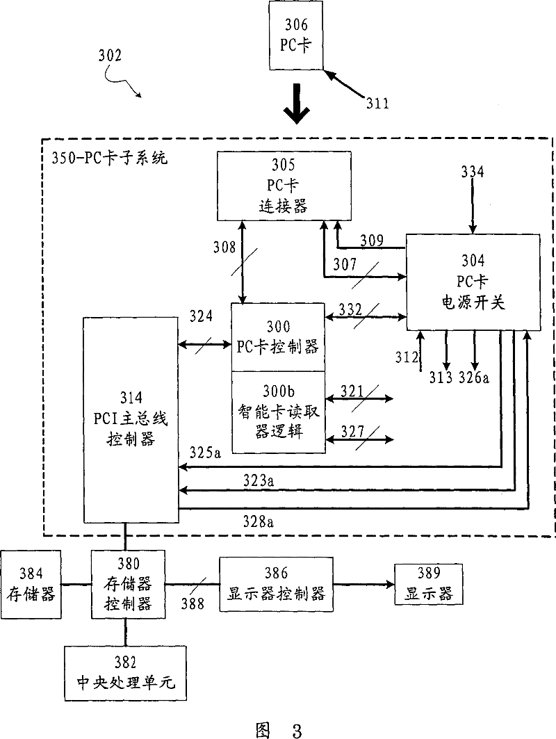
[0076] Figure 3 shows a computer system 302 according to an embodiment of the present invention. In this embodiment, computer system 302 includes a PC card subsystem 350, a memory controller 380 connected to main bus controller 314, memory 384 connected to memory controller 380, and a central processing unit 382 connected to Connect to memory controller 380. In this embodiment, the display controller 386 is connected to the memory controller 380 through an interface such as accelerated graphics port (AGP) 388 to output display signals to a display 389 such as an LCD (Liquid Crystal Display).

[0077] In this embodiment, the PC Card subsystem 350 includes a PC Card controller 300 , a PC Card connector 305 , a host bus controller 314 , and a PC Card power switch 304 . The PC card controller 300 communicates with the PC card power switch 304 through a communication interface 332 and a communication protocol.

[0078] While not wishing to be limited by the examples presented, th...


PUM


Abstract

A PC Card subsystem is used for coupling a PC card to a computer system and comprises a PC Card controller and a PC Card power switch. The PC Card controller is coupled to and operates the PC card. The PC Card power switch is used for supplying power to the PC Card and provides at least one control signal for operating the PC card.

Description

technical field [0001] The present invention relates to a PC card controller and a PC card power switch for connecting a PC card to a computer system, and more particularly to a PC card controller having a reduced pin count to facilitate more cost-effective manufacturing of PCs Card controller and PC Card power switch. Background technique [0002] PC cards (16-bit PCMCIA cards and 32-bit CardBus cards) are widely installed in computer systems, especially in notebook or laptop computers. PC Cards allow users to connect different functions such as modems and data storage to a computer system using an interchangeable method. The PC Card standard publishes specifications for card form factor, power requirements, electrical interface, etc. to ensure interoperability among many computer system manufacturers. By adhering to the PC Card standard, a computer system manufacturer can enable these modular functions on their devices through a PC Card connection. [0003] Many manufac...

Claims


Application Information

Patent Timeline
Patent Type & Authority Patents(China)
IPC IPC(8): G06F13/38G06F1/26
Inventor 尼尔·茂若李艾伦
Owner O2 MICRO INT LTD
Features
  • R&D
  • Intellectual Property
  • Life Sciences
  • Materials
  • Tech Scout
  • Unparalleled Data Quality
  • Higher Quality Content
  • 60% Fewer Hallucinations
Learn More