Arrangement for adjusting deviation of optical driver

A technology of offset device and optical drive, which is applied in the configuration/installation of the head, supporting the head and other directions, and can solve the problems of reduced operating performance, discontinuous rotational force, increased load, etc.

Inactive Publication Date: 2007-12-19
LEJIN GUANGDIAN ELECTRONIC CO LTD SHANGHAI
View PDF5 Cites 0 Cited by
  • Summary
  • Abstract
  • Description
  • Claims
  • Application Information

AI Technical Summary

Problems solved by technology

[0014] In this way, if the connection state of the rack 14 and the gear shaft 17 is different, the connection conduction angle between the rack 14 and the gear shaft 17 will be inconsistent, and when the stepper motor 15 is driven, the load will be increased, resulting in discontinuous rotational force, and it will run Performance drop

Method used


Image

  • Arrangement for adjusting deviation of optical driver
  • Arrangement for adjusting deviation of optical driver
  • Arrangement for adjusting deviation of optical driver

Examples


Embodiment Construction

[0032] The ideal embodiment of the device for adjusting the offset of the optical drive according to the present invention will be described in detail below with reference to the accompanying drawings.

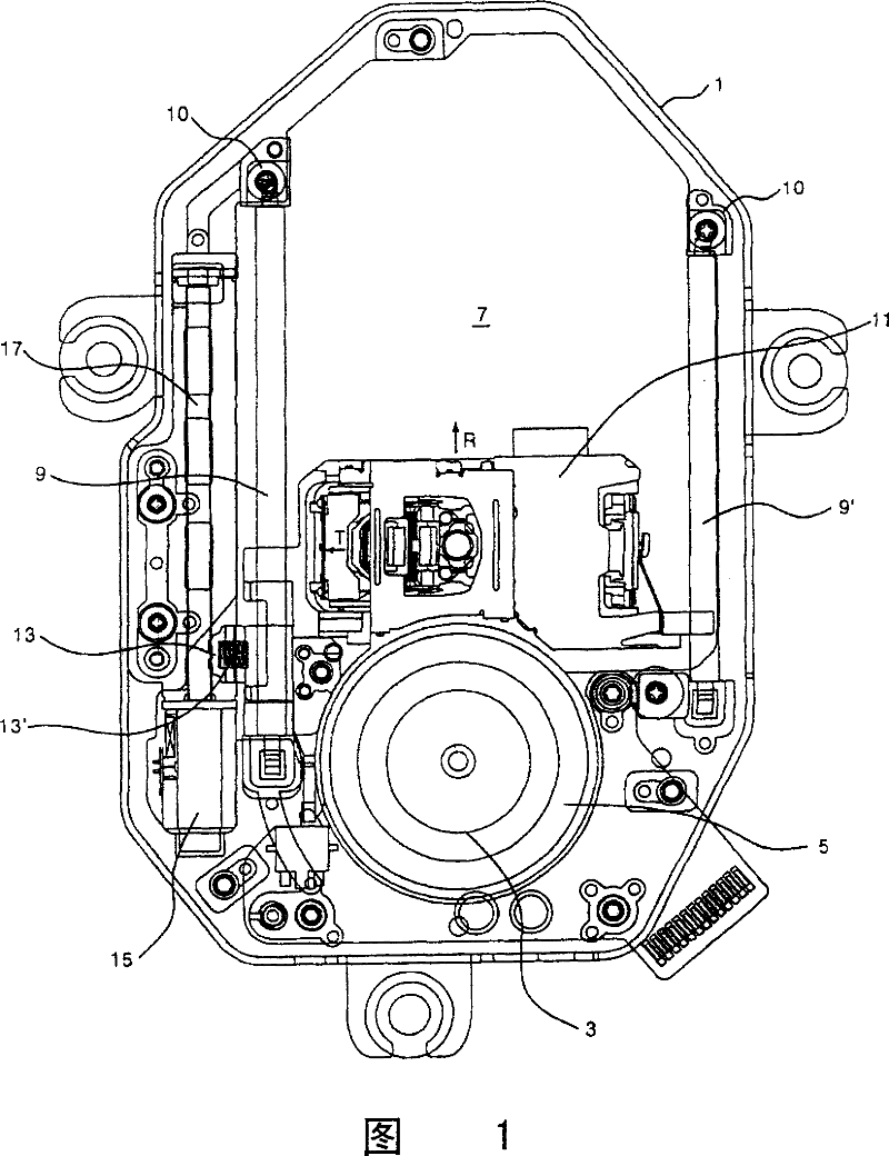
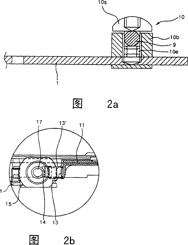
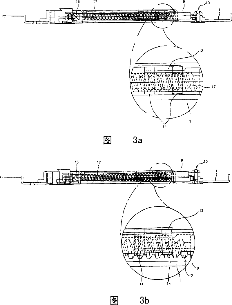
[0033] FIG. 4 is a plan view showing main components of an optical drive having an ideal example of an offset adjustment device according to the present invention. Fig. 5 is a sectional view showing main components of an example according to the present invention.

[0034] As shown in the figure, the pickup base 20 is supported and installed on the main base of the optical drive (not shown in the figure). Generally, the pickup base 20 has bumpers on it to support the main base and absorb vibration and noise.

[0035] One side of the pickup base 20 is provided with a spindle motor 22 . A spindle motor 22 provides power for the rotation of the disc. The rotation axis of the above-mentioned spindle motor 22 is the same as the axis of the turntable 24 . An optical disc is plac...


PUM


Abstract

The invention relates to a CD-ROM deviation regulating device, comprising: a gear shaft, installed on an optical pickup base, and obtaining a power from a step motor which supplies a motive power to the optical pickup and transmitting the power; at least a pickup drive shaft, installed on the optical pickup base and supporting the moving of the optical pickup; a transmission, installed on the optical pickup, engaging with the gear shaft and having a rack device for transmitting the power of the optical pickup; and a deviation regulator, which has at least one end supporting and connected with the pickup drive shaft and gear shaft, and simultaneously can regulate their heights.

Description

【Technical field】 [0001] This invention relates to optical drives. More specifically, the present invention relates to an apparatus for adjusting offset of an optical pickup in an optical drive. 【Background technique】 [0002] Figures 1 and 2 show the main components of an optical drive with an offset adjustment device according to the prior art. As shown in the figure, the pickup base 1 constituting the optical drive is generally in the shape of a plate with a certain area. A spindle motor 3 is mounted on one side of the pickup base 1 . The rotation axis of the above-mentioned spindle motor 3 is the same as the axis of the turntable 5 . An optical disc is mounted on the turntable 5 and is driven by the spindle motor 3 to rotate. [0003] A pickup window 7 is formed through the above-mentioned pickup base 1 . The pickup window 7 has a specific width from the position where the turntable 5 is installed to the opposite direction. Pickup conductors are installed along bot...

Claims


Application Information

Patent Timeline
Patent Type & Authority Patents(China)
IPC IPC(8): G11B7/08G11B21/24
Inventor 朴圣敏
Owner LEJIN GUANGDIAN ELECTRONIC CO LTD SHANGHAI
Why Eureka
Try Eureka