Temperature controlled valve core

A temperature control valve and valve core technology, applied in multi-way valves, safety valves, balance valves, etc., can solve the problems of difficult to accurately adjust the temperature setting, difficult to control the water flow, rapid changes in the water flow, etc., to achieve a stable constant temperature effect. , High reliability, accurate temperature setting effect

Inactive Publication Date: 2008-01-02
叶国荣
View PDF5 Cites 0 Cited by
  • Summary
  • Abstract
  • Description
  • Claims
  • Application Information

AI Technical Summary

Problems solved by technology

[0007] 4. In the temperature-sensitive movable valve core, cold water flows through a general cold water port, and hot water flows through a general hot water port. The water flow is not easy to control, and a slight movement of the slider may cause a sharp change in the water flow. , the temperature is difficult to adjust and set precisely

Method used


Image

  • Temperature controlled valve core
  • Temperature controlled valve core
  • Temperature controlled valve core

Examples


Embodiment 1

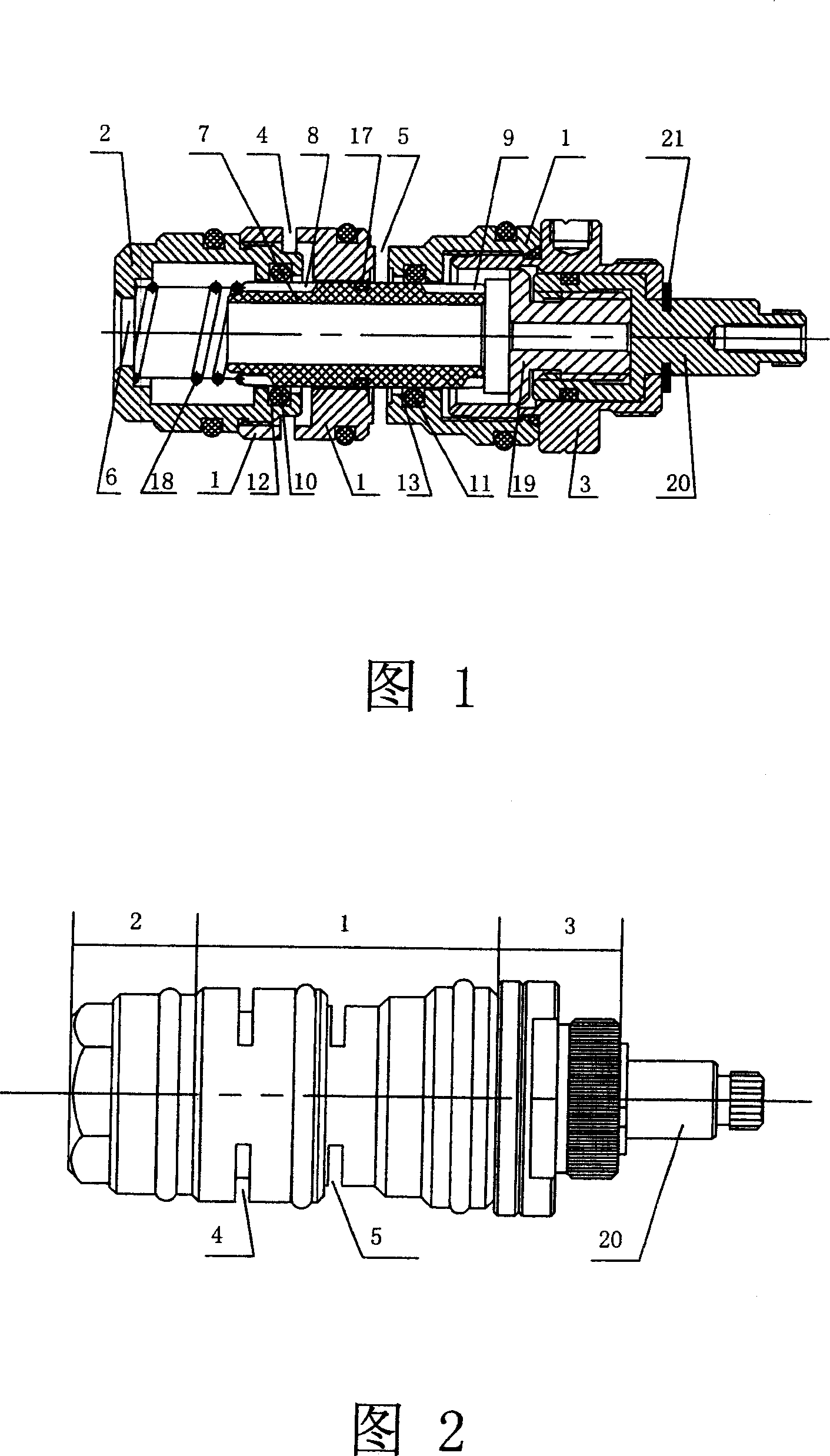
[0035] Please refer to Figure 1 and Figure 2, a temperature control valve core, including a middle sleeve 1, a water outlet sleeve 2 threaded to one end of the middle sleeve 1, and a pressure sleeve 3 threaded to the other end of the middle sleeve 1 The spool cover, the first water inlet 4 (ie hot water channel), the second water inlet 5 (ie cold water channel) is set on the middle cover 1, and the water outlet 6 (ie mixed water channel) is set on the water outlet cover 2 , a spool inner core 7 is installed in the middle sleeve 1, the main body of the spool inner core 7 is a hollow cylinder, the spool inner core 7 is limited by the inner core spring 18 and the abutment head 19, and the abutment head 19 passes through the thread and the adjustment screw rod 20 Cooperate, the adjusting screw rod 20 passes through the pressure sleeve 3 and is clamped by the collar 21, one end of the inner core spring 18 is pressed against the water outlet sleeve 2, and the other end is pressed aga...

Embodiment 2

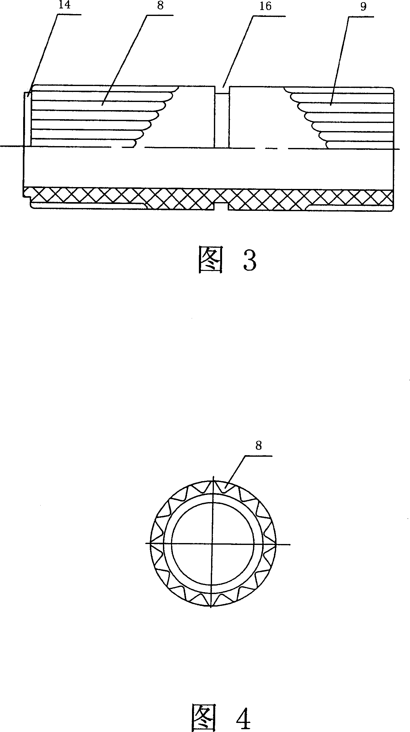
[0040] Please refer to Fig. 7, the difference between this embodiment and the first embodiment lies in the structure of the notch 15, the notch 15 is another deformation of the protrusion 14, which is used to cooperate with the outer circumference of the inner core spring 18, and its function is similar to that of the first embodiment. The protrusion 14 in Fig. 3 has exactly the same function.

Embodiment 3

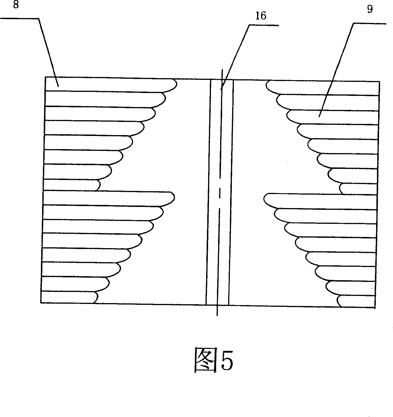
[0042] Please refer to Fig. 8, the difference between this embodiment and Embodiment 1 is that there are only two first through grooves 8 and second through grooves 9, the lengths of the two first through grooves 8 are different, and the lengths of the two second through grooves 9 are different. Different lengths.


PUM


Abstract

The temperature controlled valve core includes one middle casing with the first water inlet channel and the second water inlet channel; one water outlet casing with water outlet channel connected to one end of the middle casing and one pressing casing connected to the other end of the middle casing. Inside the middle casing, there are a valve core as an axially limited hollow cylinder, two first grooves and two second grooves on the outer surface of the valve core and in the positions near the first water inlet channel and the second water inlet channel separately; the first axially positioned elastic ring and the second elastic ring separately in the first grooves and two second grooves, and one sealing ring set between the first grooves and the second grooves. The first water inlet channel is communicated with the water outlet channel through the first grooves, and the second water inlet channel through the second grooves. The present invention has precise temperature setting, stable temperature stabilizing effect and high reliability.

Description

technical field [0001] The invention relates to a constant temperature control device, in particular to a temperature control valve core for sanitary equipment. Background technique [0002] The current thermostatic valve is more common in bathroom equipment, and its purpose is to mix cold water and hot water to provide warm water suitable for use. Now there are temperature-controlled spool products, such as Chinese patent ZL200420045079.1, which discloses a temperature-sensitive movable spool, and the inner core of the spool used in the temperature-sensitive movable spool is a sliding block that can slide axially , adjust the size of the cold water port and the hot water port by sliding the slider in the valve core, so as to realize the adjustment of the temperature of the mixed water. Due to the influence of water pressure, the amount of cold water inlet and hot water inlet will change and affect the temperature of the mixed water. The temperature-sensitive movable valve ...

Claims


Application Information

Patent Timeline
Patent Type & Authority Patents(China)
IPC IPC(8): F16K11/07F16K17/00
CPCG05D23/01
Inventor 叶国荣
Owner 叶国荣
Why Eureka
Try Eureka