Method for controlling the oil recirculation in an oil-injected screw-type compressor and compressor using this method

A compressor and screw technology, which is used in the field of controlling the oil circulation in the oil-injected screw compressor, can solve the problems of high temperature peaks of the compressor body and so on.

Inactive Publication Date: 2008-01-16
ATLAS COPCO AIRPOWER NV
View PDF7 Cites 0 Cited by
  • Summary
  • Abstract
  • Description
  • Claims
  • Application Information

AI Technical Summary

Problems solved by technology

[0007] Therefore, with these existing methods it is possible to generate a high temperature peak at the outlet of the compressor body

Method used


Image

  • Method for controlling the oil recirculation in an oil-injected screw-type compressor and compressor using this method
  • Method for controlling the oil recirculation in an oil-injected screw-type compressor and compressor using this method
  • Method for controlling the oil recirculation in an oil-injected screw-type compressor and compressor using this method

Examples


Embodiment Construction

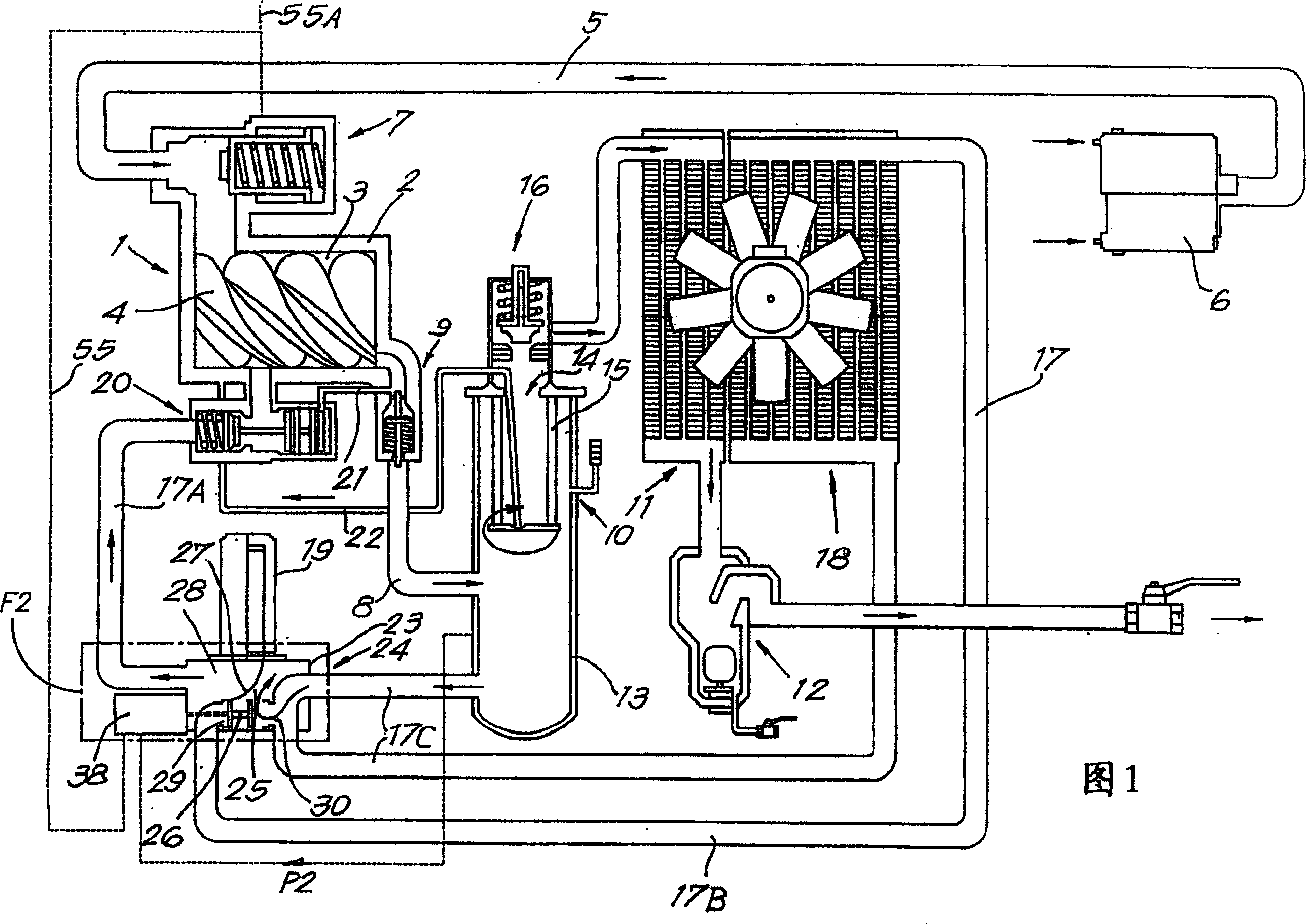
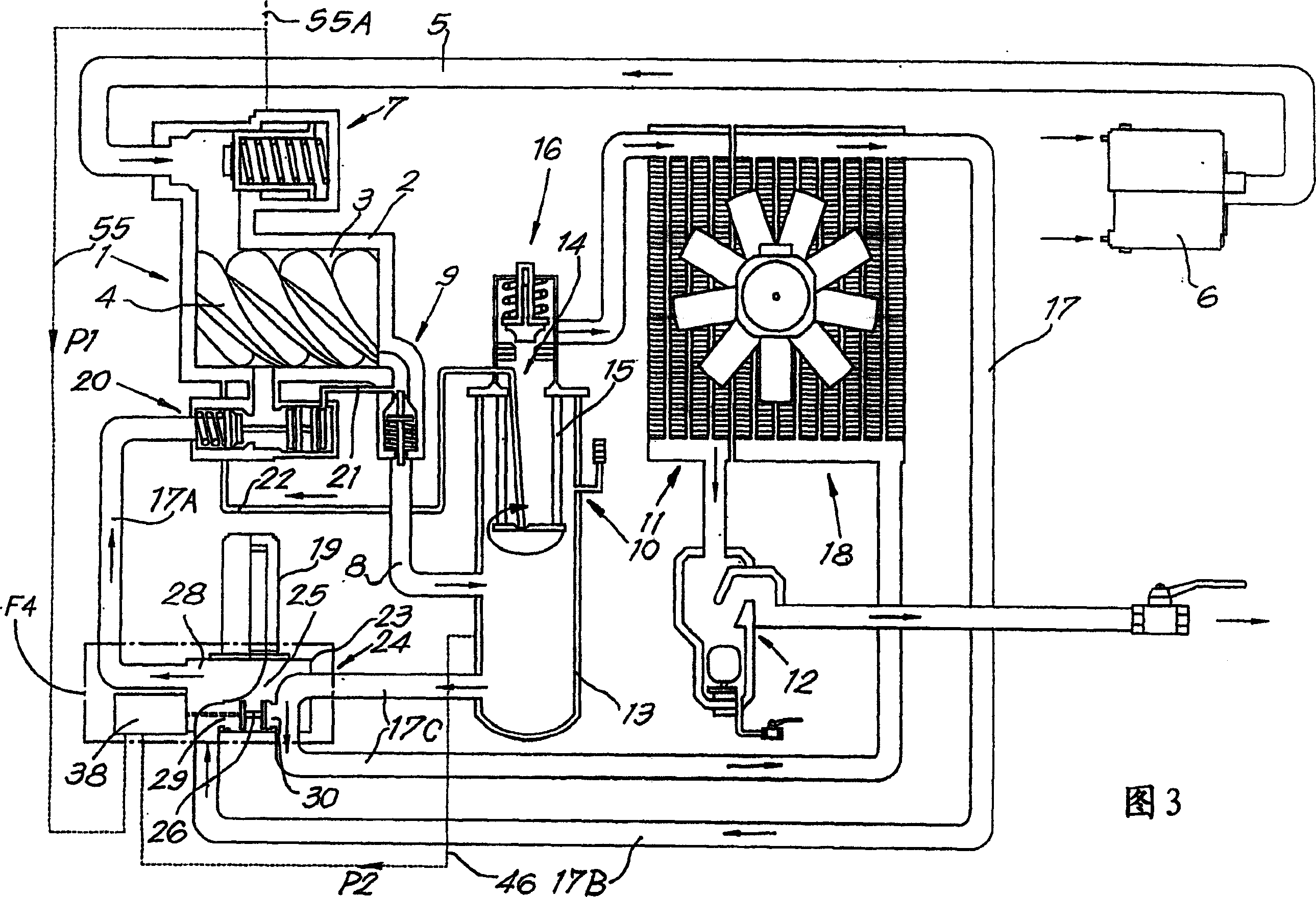
[0029] The screw compressor shown in the various figures comprises a compressor body 1 having a casing 2 enclosing a rotor chamber 3 in which are installed two cooperating helical Rotor 4. The main body of the compressor 1 is driven by a motor (not drawn in the figure).

[0030] On the inlet side, the inlet of the air intake line 5 communicates with the rotor chamber 3, and an air filter 6 and a controllable air intake valve 7 are installed in the air intake line 5, while on the outlet side, the pressure line 8 is connected to the rotor chamber 3 via an outlet valve 9, for example a return valve.

[0031] An oil separator 10 , an air cooler 11 and a water separator 12 are installed sequentially in the pressure line 8 .

[0032] Inside the oil separator 10 there is a container 13 with an outlet 14 at the top. A filter 15 is installed opposite to the outlet 14 in the container 13, and a minimum pressure valve 16 is installed in the outlet 14.

[0033] Most of the oil is coll...


PUM


Abstract

The invention relates to a method for controlling the oil recirculation in an oil-injected screw-type compressor which, between the oil separator (10) and the compressor element (1), comprises an oil recirculation conduit (17) in which an oil cooler (18) is installed which is bridged-over by a passage or bypass (30), said control taking place by means of a thermostatic valve (24) having a valve element (26) which can be moved by means of a temperature-sensitive element (34). During the transition of the screw compressor from the unloaded to the loaded condition, the effect of the temperature-sensitive element (34) temporarily is switched off at least partially, such that the valve element (26) takes a position in which, regardless of the temperature of the oil, at least the bypass (30) is open and thus the recirculation of oil from the oil separator (10) to the compressor element (1) takes place through this bypass (30).

Description

technical field [0001] The invention relates to a method for controlling oil circulation in an oil-injected screw compressor. The oil-injected screw compressor includes: a compressor main body; an intake pipeline and a pressure pipeline connected to the compressor main body; an oil separator in the pressure pipeline; the oil separator and the compressor main body An oil circulation line between them; an oil cooler installed in said circulation line; a channel or bypass across the oil cooler in the circulation line; a thermostatic valve having a valve element and controlling said circulation line; A heat sensitive element that can move the valve element. The thermal sensor measures the temperature of the circulating oil. If the measured temperature is below a certain value, the valve element opens the bypass so that separated oil can flow from the oil separator directly to the compressor body without passing through the oil cooler. If the measured temperature exceeds a certa...

Claims


Application Information

Patent Timeline
Patent Type & Authority Patents(China)
IPC IPC(8): F04C29/02F04C29/00F04C28/00F04C18/16F04C28/26F04C28/06
CPCF04C28/06F04C29/0014F04C29/021F04C18/16F04C29/02
Inventor 弗朗索瓦·L·J·特吕延伊万·A·D·努康
Owner ATLAS COPCO AIRPOWER NV
Why Eureka
Try Eureka