Self-activating power device gaining energy from power line magnetic field

A technology of power supply device and energy extraction device, which is applied to battery circuit devices, circuit devices, electromagnetic wave systems, etc., can solve the problems of self-excited power supply unable to obtain energy, hindering self-excited power supply technology, and short life cycle of laser source, etc. The effect of increasing reliability and service life, reasonable functional structure and long service life

Inactive Publication Date: 2008-01-16
西安华伟光电技术有限公司
View PDF2 Cites 1 Cited by
  • Summary
  • Abstract
  • Description
  • Claims
  • Application Information

AI Technical Summary

Problems solved by technology

However, how to obtain the primary side power supply is currently the biggest problem hindering the further development of this technology. In the past, domestic and foreign researchers generally used the method of transmitting laser energy from the low-voltage side to the high-voltage side through an optical cable. For example, foreign ABB companies and domestic companies have emerged All products adopt the laser energy delivery scheme. The disadvantages in the implementation of this kind of scheme are: ①, the life cycle of the laser source is short, only 8000-10000 hours; ②, the laser source is expensive, accounting for more than half of the cost of the whole machine ; ③, on-site maintenance is difficult
However, due to the large dynamic range of the power line current, there are still two technical difficulties in the operation of the above scheme. One is that when the primary current is less than 3A, the self-excited power supply cannot obtain enough energy; the other is that when the primary current increases to When above thousands of amps, self-excited power supply is not easy to solve the problem of harmful temperature rise and high-voltage spikes causing damage to devices, thus hindering the self-excited power supply technology from entering a fully practical level

Method used


Image

  • Self-activating power device gaining energy from power line magnetic field

Examples


Embodiment Construction

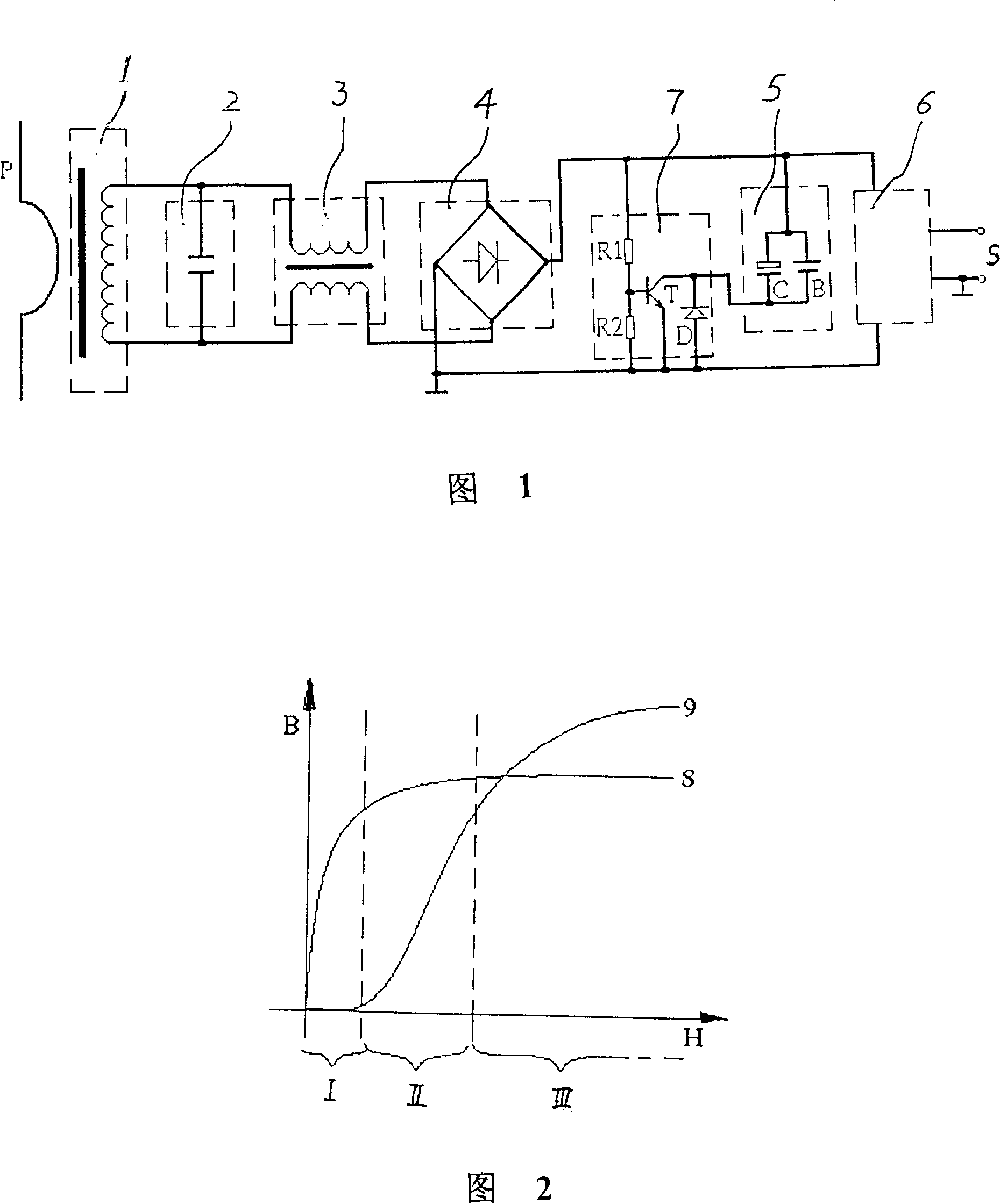
[0008] Referring to Fig. 1, the self-excited power supply device for obtaining energy from the magnetic field of the power line according to the present invention includes two parts: an energy taking device and a power supply device. The energy taking device is composed of an energy taking coil 1, a peak absorption capacitor 2 and a choke coil 3. The power supply device is composed of a rectifier circuit 4, an energy storage capacitor or battery 5, a voltage stabilizing module 6 and a charging control circuit 7.

[0009] The energy-taking coil 1 is set on the power line P, and a soft magnetic core ring with the highest possible initial permeability and a lower saturation magnetic flux is selected as the skeleton (for example, the initial permeability greater than 80,000Gs / 0e and the saturation magnetic flux less than 2.5×10 can be selected -1 Weber's soft magnetic materials), in order to form the highest possible magnetic field energy sensitivity and less saturation energy convers...


PUM


Abstract

The invention relates to a self-activate power source which obtains energy from high-energy electric magnetic field, which comprises an energy obtainer and a power source, wherein the energy obtainer is formed by an energy obtaining coil, a peak adsorption capacitor and a choke coil; the power source is formed by rectify circuit, accumulation capacitor or battery, stabilize module, and charge control circuit; the invention can obtain enough energy, without high-voltage sharp impulse to damage the rectify stabilize circuit, to support stable working power source for the separated electric inducer and other high-voltage circuit. The invention has low activate current, wider application and long service life, etc.

Description

Technical field [0001] The invention belongs to the technical field of electric power measurement, and relates to an energy transmission device that can be used to provide a stable working power supply for optically isolated electronic current transformers and other electrically isolated meters. Background technique [0002] In recent years, with the continuous improvement of grid capacity and voltage level, the research and development of electronic current transformers that use optical fiber transmission as primary and secondary insulation isolation has been highly valued at home and abroad. Among them, the structure of "active" current transformers It is generally recognized by the industry because of its superior performance and easy industrialization characteristics. However, how to obtain the primary side power supply is currently the biggest problem hindering the further development of this technology. In the past, domestic and foreign researchers generally used the method...

Claims


Application Information

Patent Timeline
Patent Type & Authority Patents(China)
IPC IPC(8): H02J17/00H02J7/00H02J50/10
Inventor 刘忠战
Owner 西安华伟光电技术有限公司
Why Eureka
Try Eureka