
A device for collecting and treating waste from a grinding wheel grinder

A processing device and grinding machine technology, applied in grinding/polishing safety devices, grinding/polishing equipment, metal processing equipment, etc., can solve problems such as difficult discharge of waste residue, overflow of waste residue and smoke, and generation of a large amount of smoke, etc., to achieve Reasonable functional structure, easy operation and simple structure

Active Publication Date: 2020-05-26
白益凡
View PDF6 Cites 0 Cited by
  • Summary
  • Abstract
  • Description
  • Claims
  • Application Information

AI Technical Summary

Problems solved by technology

[0004] In order to solve the above technical problems, the present invention provides a grinding wheel grinder waste collection and treatment device to solve the problem that many waste residues will be generated during the existing product grinding process, and these waste residues will not be collected well, which will affect the surrounding environment , and during the grinding process, the friction between the grinding wheel and the product will produce a lot of smoke, which will also affect the surrounding environment, which does not meet the needs of environmental protection production. Some existing environmental protection treatment devices are installed nearby. When processing waste residue, There will still be waste slag and flue gas overflowing, and the collected waste slag is not easy to discharge from the device

Method used


Image

  • A device for collecting and treating waste from a grinding wheel grinder
  • A device for collecting and treating waste from a grinding wheel grinder
  • A device for collecting and treating waste from a grinding wheel grinder

Examples


Embodiment

[0031] as attached figure 1 To attach Figure 9 Shown:

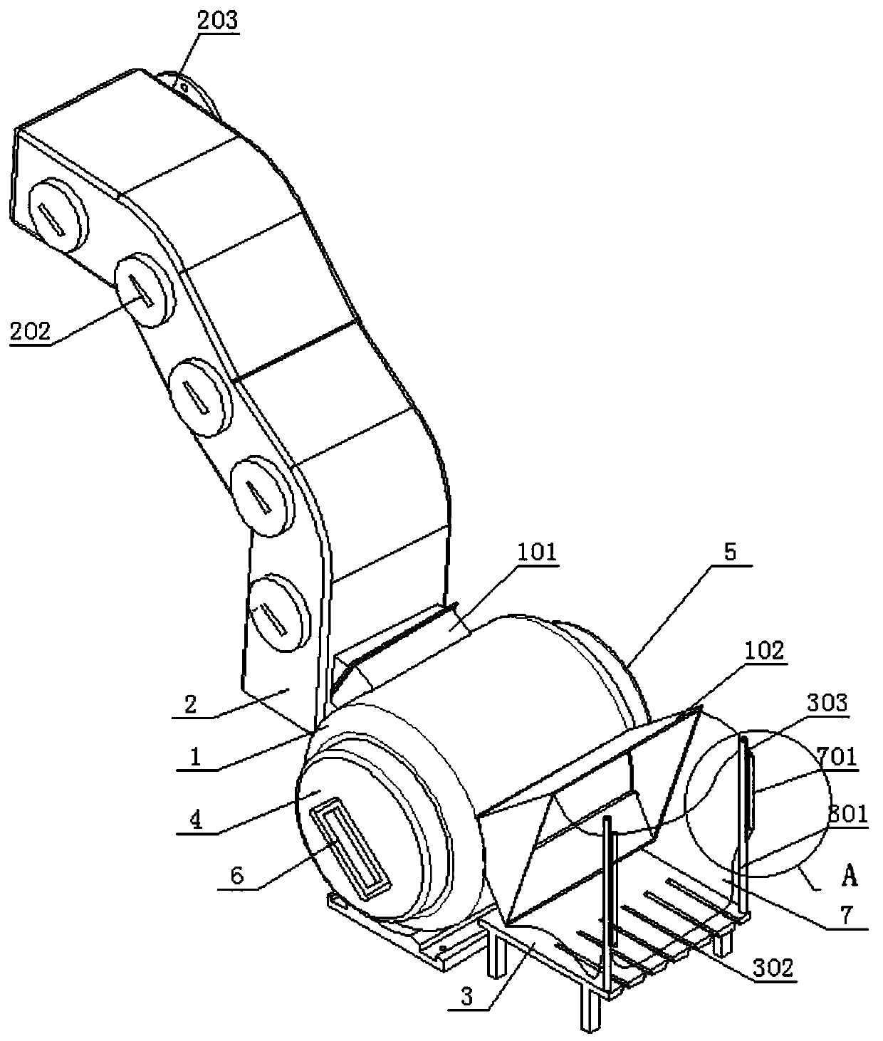
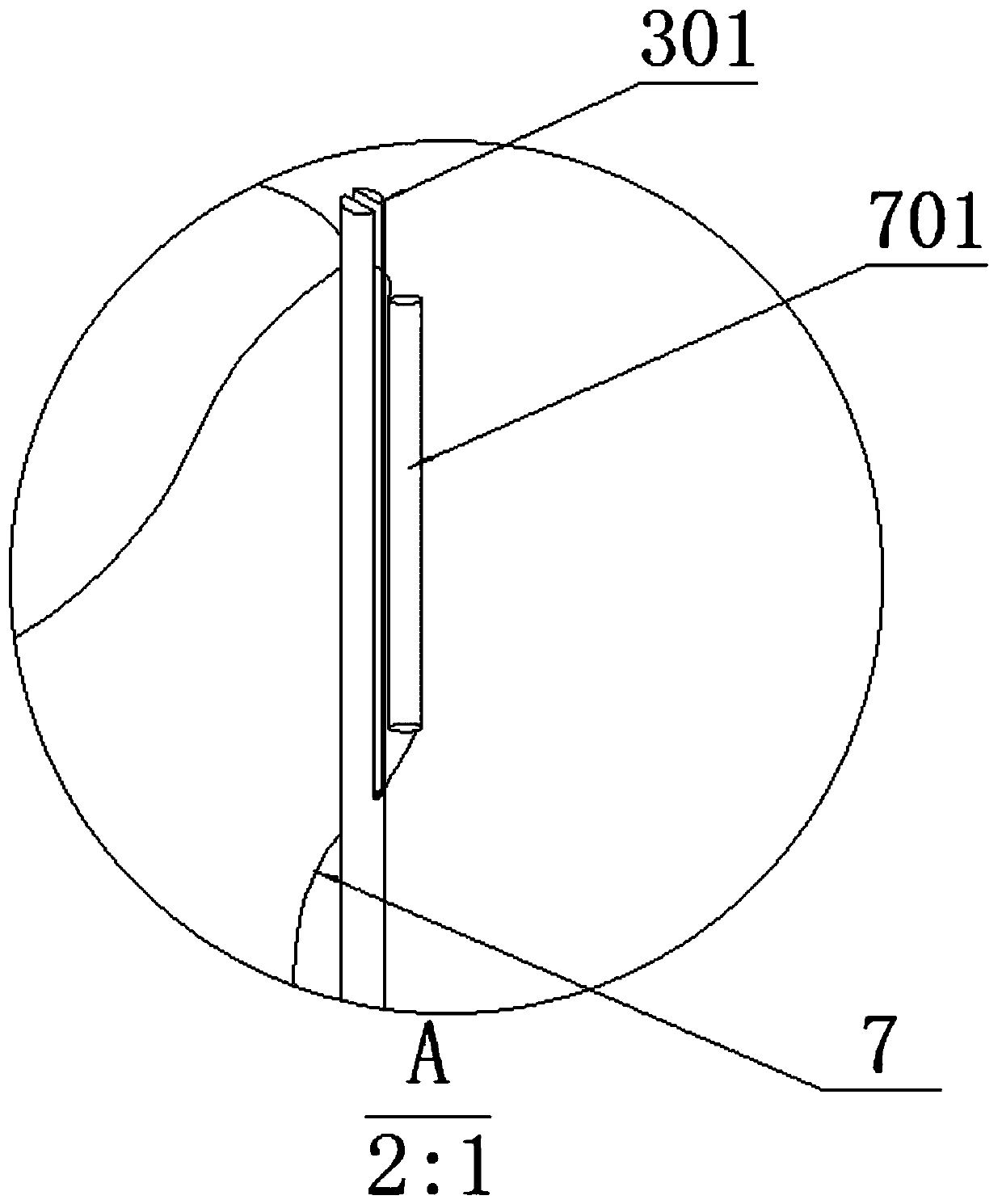
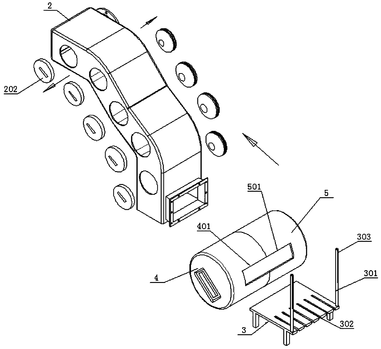
[0032] The present invention provides a grinding wheel grinder waste collection and treatment device, including: a collection seat 1, a dust outlet 101, a cover 102, a dust suction pipe 2, a mounting hole 201, a functional column 202, a flange interface 203, and a tool rack 3. Functional rod 301, fixed slot 302, through slot 303, first slag collection cabin 4, first slag inlet 401, first smoke outlet 402, first magnet 403, second slag collection cabin 5, second inlet Slag outlet 501, second smoke outlet 502, second magnet 503, handle 6, collection pocket 7 and hanging rod 701; one side of the collection seat 1 is provided with a dust outlet 101, and the other side is provided with a cover 102, and a dust suction pipe 2 is installed on the outside of the dust outlet 101; the tool rack 3 is a rectangular welded frame structure, and two function bars 301 are vertically installed on the right side of the top surface, and t...


PUM


Abstract

The invention provides a grinding wheel grinding machine waste collecting and processing device. The grinding wheel grinding machine waste collecting and processing device comprises a pull handle, a collecting bag and a hanging rod, wherein the left side and the right side of a collecting seat are provided with a dust outlet and a baffle cover respectively, a dust collecting pipe is arranged on the outer side of the dust outlet, a tool frame is of a rectangular welding frame structure, two functional rods are perpendicularly installed on the right side of the top surface of the tool frame, anda penetrating groove is formed in each of the two functional rods. The device is composed of three major parts which are a dust collection and processing device, a waste residue collecting device anda grinding tool tool-frame-supporting device in sequence from left to right, therefore, all smoke gas and waste residues can be collected; slag materials can be conveniently collected and dischargedthrough a collecting cabin of the structure; a plurality of mounting hole structures are arranged on a dust suction pipeline at the leftmost side, and therefore, dust on the inner walls of different directions of the pipeline can be conveniently cleared; and the overall structure is greatly different from that of the prior art, the structure is superior to that of the prior art, the functional structure is more reasonable, operation is convenient, and the structure is simple.

Description

technical field [0001] The invention belongs to the technical field of the structure of a waste residue treatment device during grinding by a grinder during mechanical processing, and more specifically relates to a waste collection and treatment device for a grinder grinder. Background technique [0002] There are many kinds of automotive product parts, but their production processes are roughly the same. The production process consists of casting, heat treatment, forging, and machining. In the process of processing, the product parts need to be surface treated to meet the process requirements. The grinding machine grinds the surface of the product to meet the needs of the next process production, such as bending the product, grinding the surface before the bending process, etc. [0003] Based on the above description of the optical axis grinding process, it is found that during the grinding process of the existing product parts, a lot of waste residues will be generated, an...

Claims


Application Information

Patent Timeline
Patent Type & Authority Patents(China)
IPC IPC(8): B24B55/06B24B55/12
Inventor 吴宝昕
Owner 白益凡
Learn More