Area source device

A surface light source and bottom surface technology, applied in optics, nonlinear optics, instruments, etc., can solve problems such as complex structure design, and achieve the effect of simple design structure and uniform output light

Inactive Publication Date: 2008-01-23
HONG FU JIN PRECISION IND (SHENZHEN) CO LTD +1
View PDF7 Cites 0 Cited by
  • Summary
  • Abstract
  • Description
  • Claims
  • Application Information

AI Technical Summary

Problems solved by technology

[0007] In order to solve the defect that the prior art surface light source device has complicated structural design for uniform light output, the present invention provides a surface light source device with uniform light output and simple structural design

Method used


Image

  • Area source device
  • Area source device
  • Area source device

Examples


Embodiment Construction

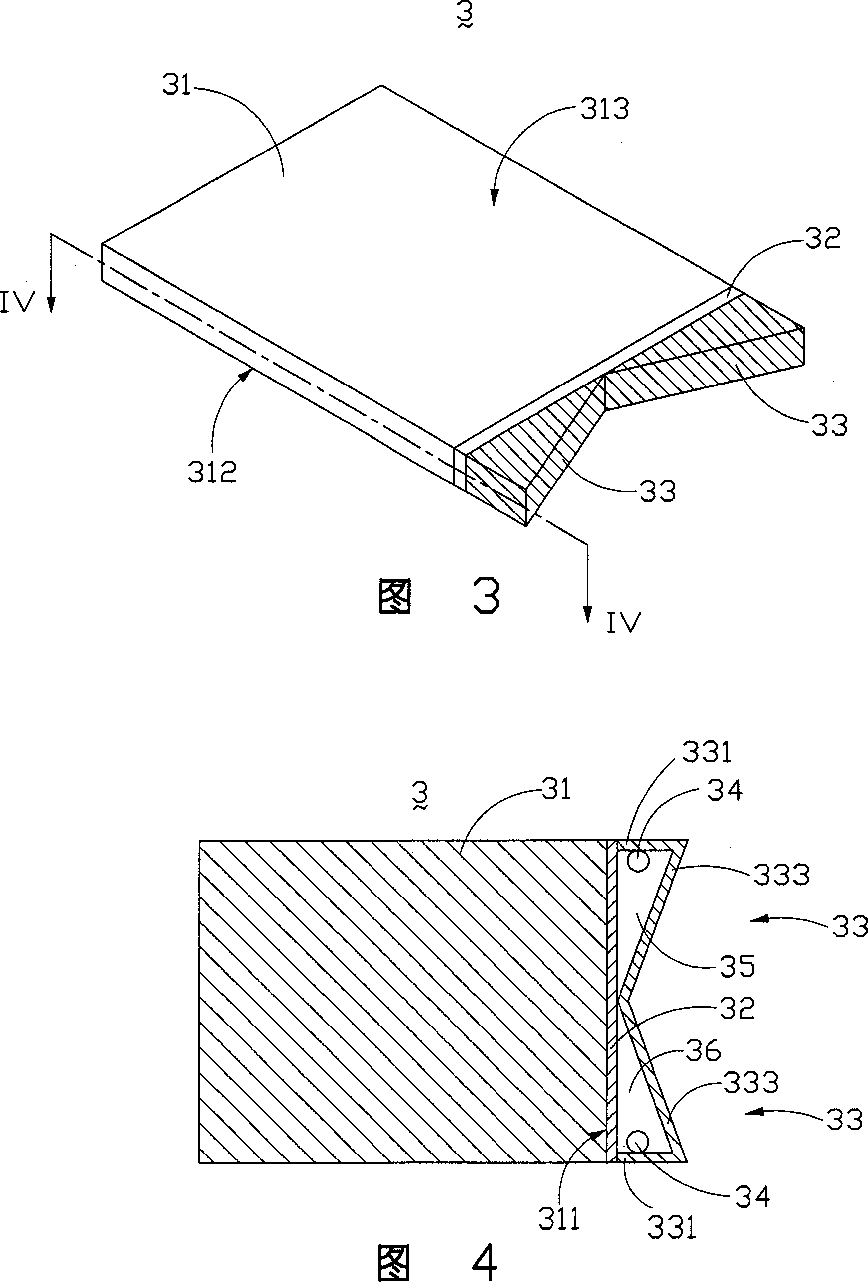
[0019] Please refer to FIG. 3 and FIG. 4 , which are respectively a perspective view of the first embodiment of the surface light source device of the present invention and a cross-sectional view of the perspective view along the IV-IV direction. The surface light source device 3 includes a light guide plate 31 , a brightness enhancement sheet 32 ​​, two reflectors 33 and two LEDs 34 . Wherein, the brightness enhancement sheet 32 ​​is attached to the light incident surface 311 of the light guide plate 31, the two reflectors 33 are V-shaped groove structures, and are symmetrically distributed with the light incident surface 311 of the light guide plate 31, including the first side The wall 331 and the second side wall 333, wherein the first side wall 331 is perpendicular to the two ends of the light incident surface 311 of the light guide plate 31, and the two ends of the second side wall 333 are respectively connected to the first side wall 331 and the two ends of the light gui...


PUM


Abstract

The invention discloses an area light source equipment, it includes at least a light emitting diode, at least a reflector and an optical leading board, which at least includes an incident face, an emergent face, an underside which is according to the emergent face, and several flanks. The reflector is a groove with two lateral walls, it is located on one side of the optical leading board and clamp with it to form a cavity to contain the light emitting diode.

Description

【Technical field】 [0001] The invention relates to a surface light source device, in particular to a surface light source device using a light emitting diode as a light source. 【Background technique】 [0002] A surface light source device of a liquid crystal display usually adopts a line light source or a point light source as a light source. The line light source is generally a cold cathode ray tube (Cold Cathode Fluorescent Lamp, CCFL for short), and the point light source is generally a light-emitting diode (Light-Emitting Diode, LED for short). [0003] Please refer to FIG. 1 , which is a perspective view of a surface light source device in the prior art. The surface light source device 1 includes a plurality of light sources 11 and a light guide plate 12, a plurality of arc-shaped grooves 122 are evenly formed on the incident surface 121 of the light guide plate 12, and the plurality of point light sources 11 are light-emitting diodes, which are respectively arranged on...

Claims


Application Information

Patent Timeline
Patent Type & Authority Patents(China)
IPC IPC(8): G02F1/13357G02F1/1335
Inventor 宋长志
Owner HONG FU JIN PRECISION IND (SHENZHEN) CO LTD
Why Eureka
Try Eureka