
Lnear motor possessing dual winding element of mover

A technology of winding unit and linear motor, applied in the direction of electric components, electrical components, electromechanical devices, etc., can solve the problems of long signal response time, low motion rigidity, poor anti-interference ability, etc.

Inactive Publication Date: 2008-02-13
ZHEJIANG ZHONGKE DERUN TECH
View PDF3 Cites 0 Cited by
  • Summary
  • Abstract
  • Description
  • Claims
  • Application Information

AI Technical Summary

Problems solved by technology

[0003] In order to overcome the defects of poor anti-interference ability, long response time to signals and low motion rigidity of existing linear motors, a linear motor with strong anti-interference ability, rapid response to signals and strong motion rigidity is provided

Method used


Image

  • Lnear motor possessing dual winding element of mover

Examples


specific Embodiment approach 1

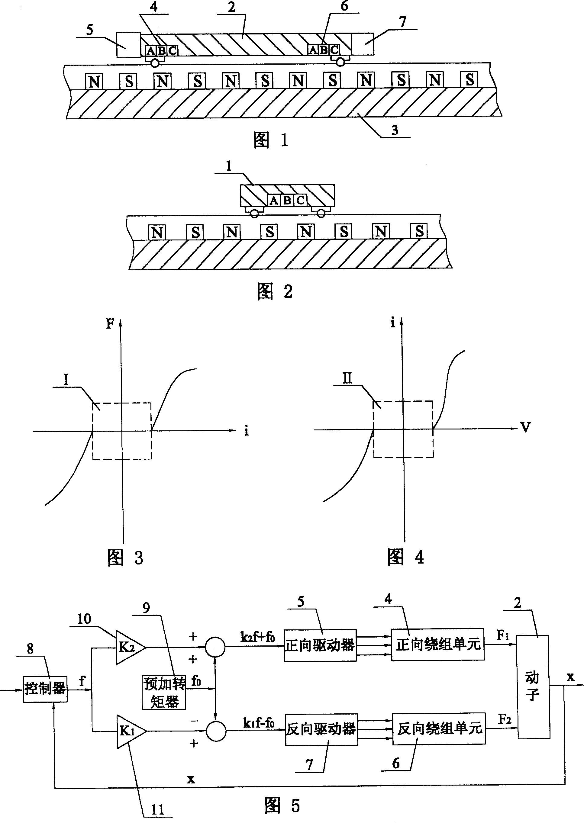
[0005] Specific Embodiment 1: The present embodiment will be specifically described below with reference to FIG. 1 . It consists of a mover 2, a stator 3, a forward winding unit 4, a forward driver 5, a reverse winding unit 6 and a reverse driver 7, and the forward winding unit 4 and the reverse winding unit 6 are longitudinally arranged on the side of the mover 2. At both ends, the forward driver 5 controls the direction and magnitude of the current in the forward winding unit 4 , and the reverse driver 7 controls the direction and magnitude of the current in the reverse winding unit 6 .

specific Embodiment approach 2

[0006] Specific Embodiment 2: The present embodiment will be specifically described below with reference to FIG. 5 . The difference between this embodiment and Embodiment 1 is that it also includes a controller 8, a first proportional gainer 10, a second proportional gainer 11 and a pre-torque 9, and the controller 8 receives the feedback from the mover 2 Displacement signal x and send out torque signal f, one way of torque signal f and the second proportional gain K of the first proportional gainer 10 2 After being multiplied with the signal f sent by the pre-torque device 9 0 superimposed and put the generated second signal K 2 f+f 0 Delivered to the forward driver 5, the forward driver 5 controls the forward winding unit 4, and the other path of the torque signal f is connected with the first proportional gain K of the second proportional gainer 11 1 Subtract the signal f sent by the pre-add torque device 9 after multiplication 0 and put the generated first signal K 2 ...

specific Embodiment approach 3

[0007] Embodiment 3: The difference between this embodiment and Embodiment 2 is that the first proportional gain K 1 and the second proportional gain K 2 The value of is also one-half.


PUM


Abstract

The invention discloses linear motor possessing two mover windings capable of generating electromagnetic forces in opposite directions. Linear motor consists of mover, stator, positive direction winding element, positive direction drive, negative direction winding element, and negative direction drive. Positive direction winding element and negative direction winding element are set at two ends of mover longitudinally. Positive direction drive controls direction and magnitude of current in positive direction winding element. Negative direction drive controls direction and magnitude of current in negative direction winding element. Since electromagnetic forces are not disappeared, mover can resist disturbing force so as to possess good rigidity at rest. Since current is never equal to zero, and in not sensing zone, thus response of linear motor is quick. Advantages of the invention are: novel design and easy of popularization.

Description

Technical field: [0001] The invention belongs to the field of linear motors, in particular to a linear motor with two mover winding units capable of generating electromagnetic forces in opposite directions. Background technique: [0002] The existing linear motor is shown in Figure 2. When the mover 1 is at rest, the current in the three-phase winding of the mover 1 should be 0. At this time, there is no electromagnetic force on the mover 1 except gravity. At this time, the The anti-interference ability of mover 1 is extremely poor, and any external force may cause it to displace along the guide rail, affecting the positioning accuracy of the linear motor. Figure 3 is the relationship curve between the winding current i in the mover 1 and the electromagnetic force F on the mover 1. When the winding current i is close to 0, there is a non-inductive band I where the electromagnetic force is 0. Therefore, when the winding current in the mover 1 changes from When 0 starts to ri...

Claims


Application Information

Patent Timeline
IPC IPC(8): H02K41/02H02K33/18
Inventor 郝双晖宋宝玉郝明晖
Owner ZHEJIANG ZHONGKE DERUN TECH
Learn More