
Tripolar field emission display of bottom grating structure and process for preparing same

A display and bottom grid technology, applied in cold cathode manufacturing, electrode system manufacturing, discharge tube/lamp manufacturing, etc., can solve problems such as pollution, high device manufacturing costs, and high device material requirements

Active Publication Date: 2008-03-12
郑州佛光发电设备股份有限公司
View PDF3 Cites 0 Cited by
  • Summary
  • Abstract
  • Description
  • Claims
  • Application Information

AI Technical Summary

Problems solved by technology

However, the formed gate current is relatively large, and the requirements for the material of the device are relatively high. During the manufacturing process of the device, the carbon nanotube cathode is easily damaged and polluted to a certain extent. This is its disadvantage.
[0004] At present, the materials used to make control grids by various manufacturing companies or research institutions are different, but most of them use special special materials and special manufacturing processes, which brings a series of problems. Problems, such as: high device manufacturing cost; complicated manufacturing process; too harsh manufacturing process conditions, unable to carry out large-scale manufacturing, etc.

Method used


Image

  • Tripolar field emission display of bottom grating structure and process for preparing same
  • Tripolar field emission display of bottom grating structure and process for preparing same

Examples


Embodiment Construction

[0046] The present invention will be further described below in conjunction with the accompanying drawings and embodiments, but the present invention is not limited to these embodiments.

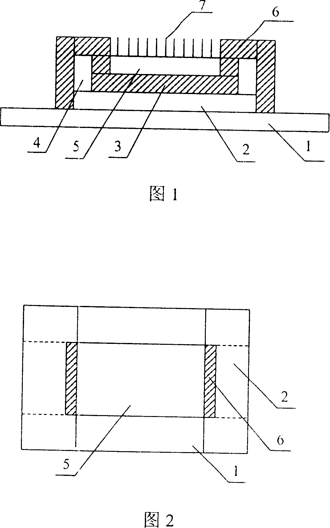
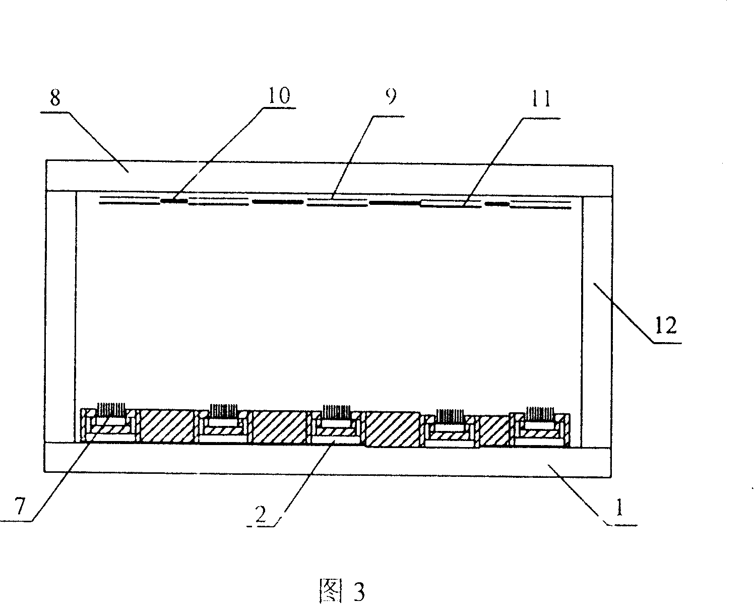
[0047] As shown in Figures 1, 2, and 3, it includes a sealed vacuum chamber composed of cathode panel glass [1], anode panel glass [8] and glass enclosure [12]. There are printed on the cathode panel glass [1] The carbon nanotube cathode [7] and the bottom gate structure control grid for controlling the electron emission of carbon nanotubes [7], there is a photolithographic tin indium oxide film layer [9] on the anode panel glass [8] and prepared in Phosphor powder layer [11] above tin indium oxide thin film layer [9]. The control grid part is located at the bottom and both sides of the carbon nanotube cathode, and is used to control the electron emission of the carbon nanotube cathode. The control grid parts on both sides have enhanced effect on the electron emission of the carbon nanotube...


PUM


Abstract

This invention relates to a three-stage field-emission display of a carbon nm tube cathode with a bottom grating structure and its manufacturing technology, among which, the display includes a sealing vacuum cavity made up of a cathode panel, an anode panel and a glass surrounding frame, the printed carbon nm tube cathode and a bottom-grating structure control grid controlling the electronic emission of the tube are set on the cathode panel, a photo-etched SnIn oxide film layer and a phosphor powder layer prepared on the film layer are set on the anode panel.

Description

technical field [0001] The invention belongs to the fields of vacuum science and technology, nano science and technology, flat display technology and microelectronic technology, and relates to the manufacture of devices for field emission flat panel displays, in particular to devices for field emission displays with a triode structure of carbon nanotube cathodes The content of production, in particular, relates to the production process of field emission flat display devices with bottom gate structure, carbon nanotube cathode, and triode structure. Background technique [0002] Carbon nanotubes are a special cold cathode material that can emit a large amount of electrons only under the action of an external voltage, which is determined by its special structure. For field emission flat display devices using carbon nanotubes as cathode materials, in order to reduce production costs to the greatest extent and reduce the operating voltage of the overall device, it is convenient ...

Claims


Application Information

Patent Timeline
Patent Type & Authority Patents(China)
IPC IPC(8): H01J31/12H01J29/02H01J29/46H01J1/304H01J1/46H01J9/02
Inventor 李玉魁
Owner 郑州佛光发电设备股份有限公司
Learn More