Long stator motor

A motor and long stator technology, applied in the field of long stator motors, can solve the problems of increasing the current intensity, increasing the cross section of cables, and the inability to realize the layout of grooves, etc., and achieve the effect of large acceleration and high acceleration value

Inactive Publication Date: 2008-03-26
SIEMENS AG
View PDF3 Cites 0 Cited by
  • Summary
  • Abstract
  • Description
  • Claims
  • Application Information

AI Technical Summary

Problems solved by technology

On the other hand, it is also not possible to increase the cable cross-section in order to increase the current intensity as much as possible, because slots that are too wide do not make it possible to lay the slots for the required cable windings in a three-phase AC motor
There is also no known suitable material for the stator core capable of achieving a high flux while withstanding high current intensities

Method used


Image

  • Long stator motor

Examples


Embodiment Construction

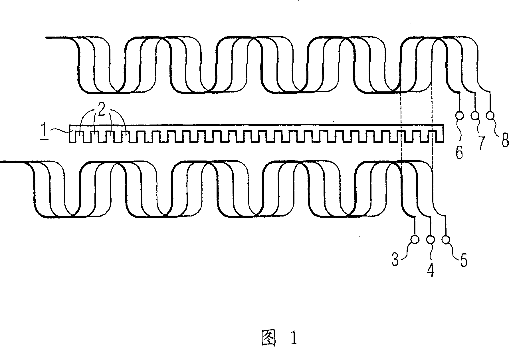
[0018] The stator core 1 shown in section has a sequence of grooves 2 . These grooves 2 serve to accommodate the cable windings 3 to 8 . It has hitherto been common to accommodate only three cable windings 3 to 5 of a three-phase AC system. The cable windings 3 to 5 each extend every second groove 2 so that the individual cable windings are evenly distributed.

[0019] In the case of a long stator motor according to an embodiment of the invention, three further cable windings 6 to 8 are laid in the same groove 2 . Here, the aforementioned cable windings 3 to 5 form a first layer, while the other cable windings 6 to 8 form a second layer. The grooves 2 do not have to be wider than in the known embodiments, but only deeper, which does not impair the stability of the stator core 1 . Wider grooves 2 are not possible for spatial reasons. The other cable windings 6 to 8 are laid relative to the previously mentioned cable windings 3 to 5 in such a way that in each groove 2 there ...


PUM


Abstract

The invention relates to a long stator motor, particularly for driving a magnetic levitation transport system, comprising a stator iron (1), inside of which grooves (2) for accommodating cable windings (3 to 8) are provided. According to the invention, at least two cable windings (3 to 5 and 6 to 8) are placed one above the other by running at least two cables inside each groove (2).

Description

technical field [0001] The invention relates to a long stator motor, in particular for driving a magnetic levitation vehicle, with a stator core in which grooves are provided for receiving cable windings. Background technique [0002] Such long stator motors are also known as linear motors, which usually have multiple stator laminations. Each stator lamination consists of a stator core mounted in said groove and some cable windings extending in the groove. Three cable windings for the three phases run in a three-phase AC motor and the grooves required for this are also arranged offset from one another. [0003] Especially when starting a locomotive driven by an electric motor with a long stator, the magnetic flux achieved in the stator core by known devices is not sufficient to achieve the desired acceleration of the locomotive. The reason for this is that the cable winding cannot withstand the amperage required for a sufficiently high magnetic flux. This current strength...

Claims


Application Information

Patent Timeline
Patent Type & Authority Patents(China)
IPC IPC(8): B60L13/03H02K41/02H02K3/28H02K41/03
CPCH02K3/28B60L13/03H02K41/031H02K2203/15B60L2200/26
Inventor 冈特·瓦格纳莱因哈德·霍夫曼本诺·韦斯沃尔夫冈·斯佩思乔格·莱姆弗尔罗伯特·施密德鲁迪格·波利福尔克-亨纳·瓦格纳
Owner SIEMENS AG
Why Eureka
Try Eureka