
Thermal module and manufacturing method thereof

A heat dissipation module and heat dissipation device technology, applied in heat exchange equipment, lighting and heating equipment, heat transfer modification, etc., can solve problems such as unsafe heat dissipation, unstable contact thermal resistance, etc., to ensure heat dissipation safety, contact heat The effect of reducing resistance and preventing overflow

Inactive Publication Date: 2008-03-26
HONG FU JIN PRECISION IND (SHENZHEN) CO LTD +1
View PDF5 Cites 0 Cited by
  • Summary
  • Abstract
  • Description
  • Claims
  • Application Information

AI Technical Summary

Problems solved by technology

[0007] In order to solve the problem of unstable contact thermal resistance and unsafe heat dissipation between the base of the heat dissipation fin and the heating element of the heat dissipation device in the prior art, the purpose of the present invention is to provide a thermal contact between the base of the heat dissipation fin and the heating element. Thermal module with stable resistance and safe heat dissipation

Method used


Image

  • Thermal module and manufacturing method thereof
  • Thermal module and manufacturing method thereof
  • Thermal module and manufacturing method thereof

Examples


Embodiment Construction

[0026] The present invention will be further described in detail below in conjunction with the accompanying drawings.

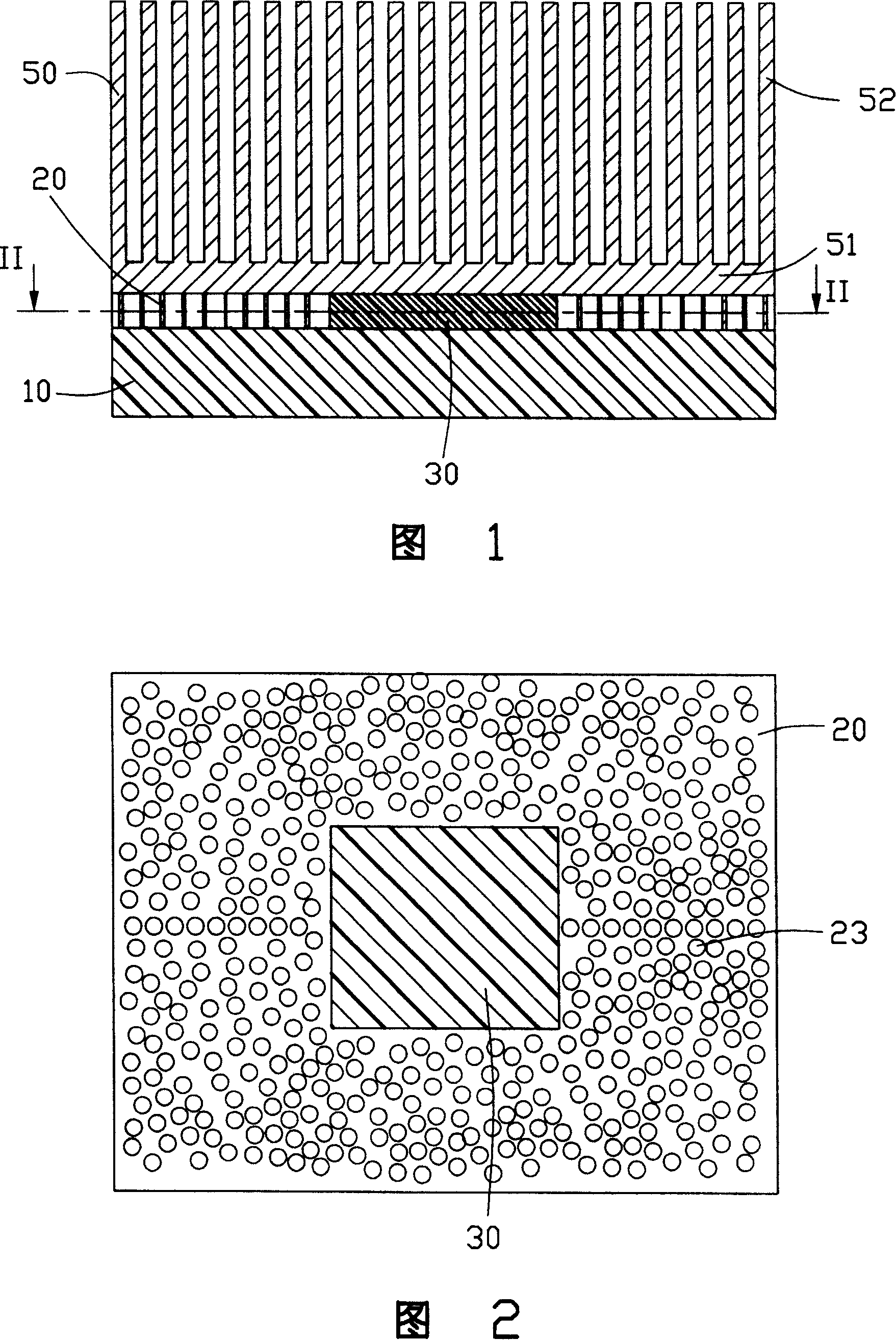
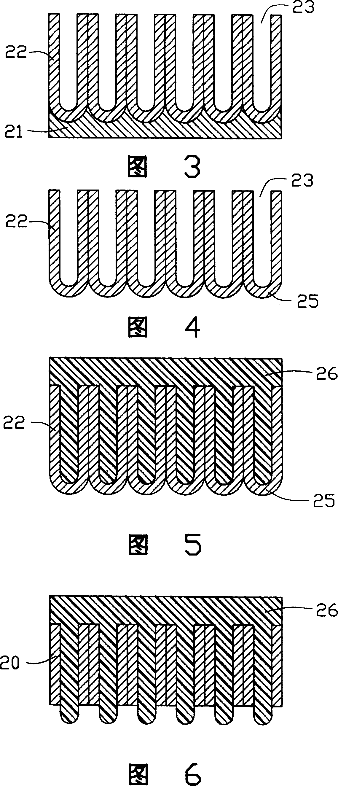
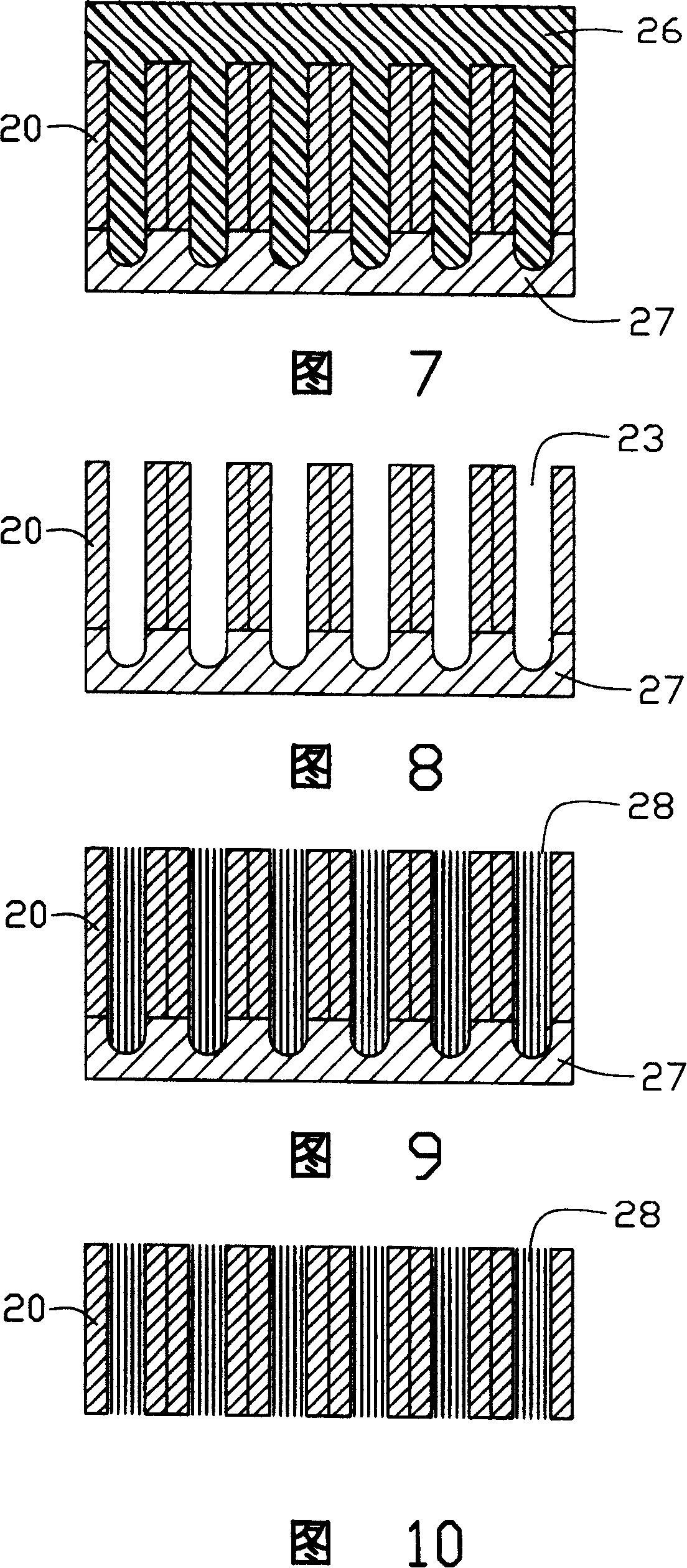
[0027] Referring to Fig. 1 and Fig. 2, the heat dissipation module provided by the present invention includes: a heating element 10; a heat dissipation device 50 comprising a base 51 and a plurality of heat dissipation fins 52 extending from the base 51; 10 between the thermal interface material 30 and the porous film 20 ; wherein, the porous film 20 is arranged around the thermal interface material 30 , and carbon nanotubes 28 grow in the holes 23 of the porous film 20 .

[0028] The heating element 10 includes electronic devices such as a central processing unit (CPU), a power transistor, a video graphics array chip (VGA), and a radio frequency chip. In this embodiment, the heating element 10 is a central processing unit (CPU).

[0029] The heat sink 50 includes air-cooled radiators, water-cooled radiators, heat pipe radiators, etc. In this embodiment, the ...


PUM

PropertyMeasurementUnit
thicknessaaaaaaaaaa
thicknessaaaaaaaaaa
pore sizeaaaaaaaaaa

Abstract

A thermal assembly includes a heat source ( 10 ), a heat sink ( 50 ), a thermal interface material ( 30 ) and a porous membrane ( 20 ). The heat sink is over the heat source. The thermal interface material is enclosed with the porous membrane, with both being between the heat source and the heat sink. The porous membrane has a number of holes ( 23 a) in which a number of carbon nanotubes ( 28 ) are provided. A method for fabricating the thermal assembly includes the following steps. The heat source having a surface is provided, wherein the surface defines a central part. The thermal interface material is coated onto the central part of the surface of the heat source. The thermal interface material is enclosed with the porous membrane, the porous membrane having the holes in which the carbon nanotubes are provided. The heat sink is attached to the heat source.

Description

【Technical field】 [0001] The invention relates to a heat dissipation module and a preparation method thereof, in particular to a heat dissipation module with a thermal interface material between a heating element and a radiator and a preparation method thereof. 【Background technique】 [0002] At present, the existing heat dissipation methods for semiconductor devices such as CPU and other heating elements mainly use air convection cooling, and radiators with heat dissipation fins are the most widely used. [0003] Initially, the contact mode between the heat sink and the heating element is mostly that the base of the heat dissipation fin is in direct contact with the heating element. The Chinese mainland patent with the announcement number CN2253493Y published on April 30, 1997 discloses a cooling device, which is mainly made of cooling fins with a fan. The air convection is formed by the fan, and the heat is conducted from the cooling fins to the surrounding air to improve...

Claims


Application Information

Patent Timeline
Patent Type & Authority Patents(China)
IPC IPC(8): H01L23/34G06F1/20
CPCB82Y10/00F28F2013/006H01L23/373F28F13/00H01L23/433H01L23/3733H01L2924/0002H01L2924/00
Inventor 颜士杰林国隆
Owner HONG FU JIN PRECISION IND (SHENZHEN) CO LTD
Learn More