LSI inspection method and apparatus, and LSI tester

An inspection method and inspection device technology, applied to measuring devices, instruments, measuring electronics, etc., can solve problems such as rising costs and misjudgment of good products as defective products

Inactive Publication Date: 2008-04-02
PANASONIC CORP
View PDF6 Cites 0 Cited by
  • Summary
  • Abstract
  • Description
  • Claims
  • Application Information

AI Technical Summary

Problems solved by technology

However, in this case, first of all, it is difficult to inspect the high-speed operating circuit itself installed in the inspection target LSI
Therefore, when the circuit inspection is not sufficient, it is possible to misjudge a good product as a defective product
The cost will also increase due to the increase in the area of ​​the LSI

Method used


Image

  • LSI inspection method and apparatus, and LSI tester
  • LSI inspection method and apparatus, and LSI tester
  • LSI inspection method and apparatus, and LSI tester

Examples


Embodiment Construction

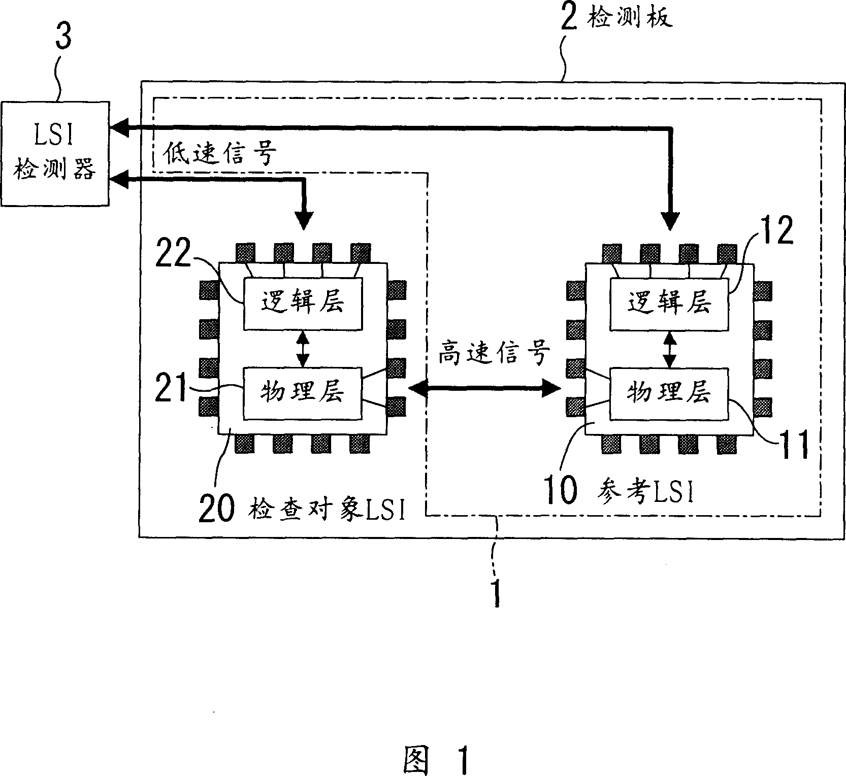
[0033] Hereinafter, embodiments of the present invention will be described with reference to the drawings. It should be mentioned that in this specification, high-speed interfaces specifically refer to IEEE1394, USB, etc., with a communication speed of several hundred Mbps or more; and low-speed interfaces, specifically, interfaces with a communication speed of several tens of Mbps or less.

[0034] (1st embodiment)

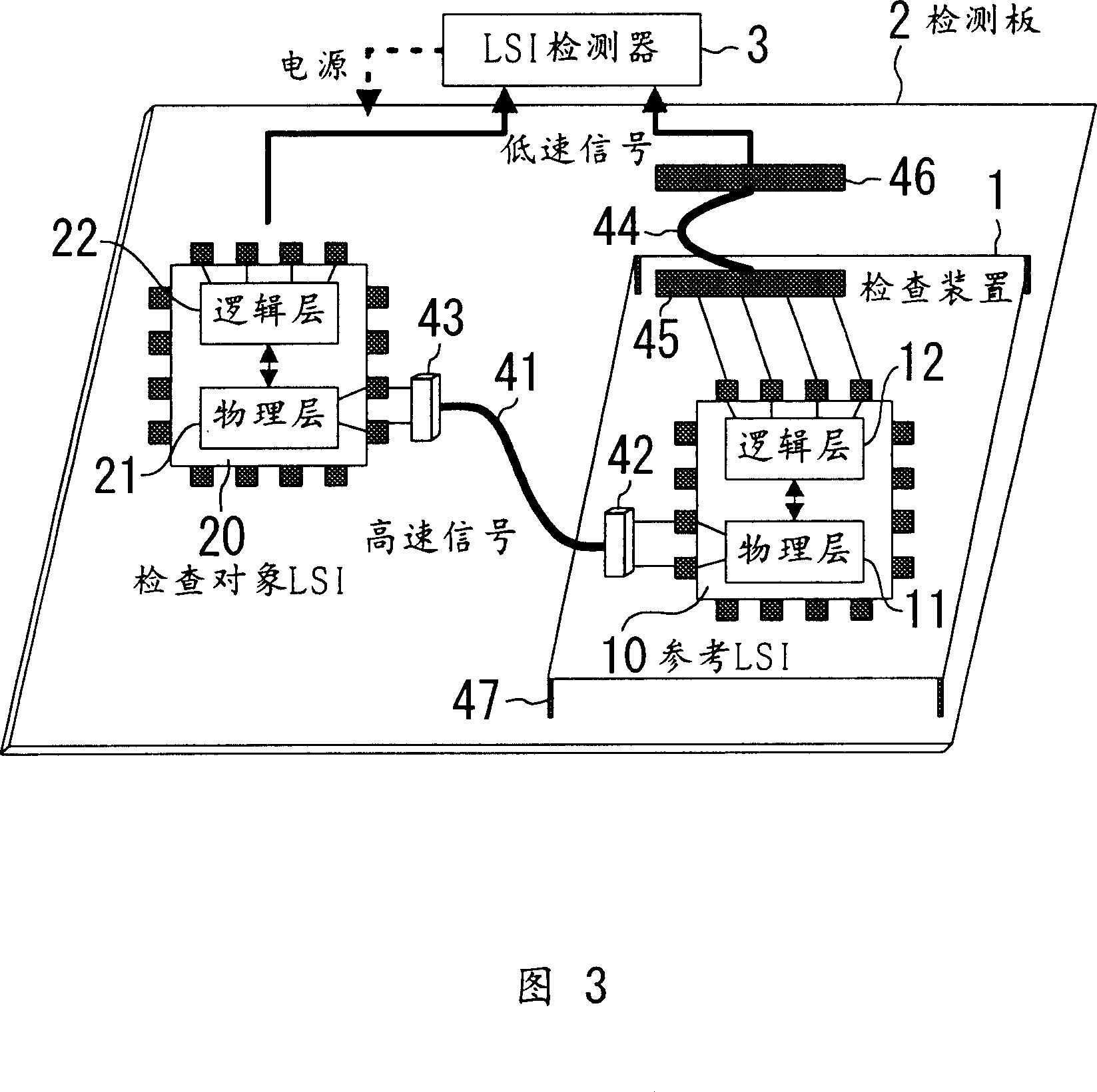
[0035] FIG. 1 shows the configuration of an LSI inspection system according to a first embodiment of the present invention. In FIG. 1 , the inspection target LSI 20 has a physical layer unit 21 having a function of connecting to the outside of the LSI at high speed, and a logical layer unit 22 connected to the physical layer unit 21 and having a function of connecting to the outside of the LSI at a low speed. . For example, in an LSI equipped with IEEE1394a-2000, the physical layer has drivers, receivers, serializers, deserializers, and mediation circuits for h...


PUM


Abstract

A test of an LSI device under test (20) including a physical layer section (21) which has a high-speed interface function is performed. An LSI device test unit (1) including a reference LSI device (10) which has already been confirmed as being non-defective is placed on a test board (2), and high-speed pins of the LSI devices (10, 20) are connected to each other. An LSI tester (3) accesses logical layer sections (12, 22) at a low speed to control a high-speed communication between physical layer sections (11, 21) and read received data, and determines whether or not the LSI device under test (20) is defective.

Description

technical field [0001] The present invention relates to an inspection of an LSI mounted with a high-speed interface. Background technique [0002] So far, when inspecting LSIs equipped with high-speed interfaces such as IEEE 1394 and USB, the inspection is carried out in such a way that the high-speed signals input to the LSI are directly supplied from the LSI detector, and the high-speed signals output from the LSI are directly read into the In an LSI detector (for example, refer to Patent No. 3058130). [0003] FIG. 9 is a diagram showing the configuration of a conventional LSI inspection system. In FIG. 9 , the physical layer unit 21 having the high-speed interface function in the LSI 20 to be inspected placed on the inspection board 52 is inspected. [0004] When checking the signal reception of the physical layer unit 21 , a high-speed signal is directly sent from the LSI detector 53 to the physical layer unit 21 . The physical layer unit 21 converts the received hig...

Claims


Application Information

Patent Timeline
Patent Type & Authority Patents(China)
IPC IPC(8): G01R31/3181G01R31/319G01R31/3193
CPCG01R31/31905G01R31/31932
Inventor 金光明彦伊藤亘渡边昭彦野崎史郎增田智充
Owner PANASONIC CORP
Why Eureka
Try Eureka