

Image display device having inspection terminal
a technology of image display device and inspection terminal, which is applied in the direction of static indicating device, identification means, instruments, etc., can solve the problems of increasing the cost of inspection device and the inability to accurately inspect each liquid crystal panel, and achieve the effect of accurate inspection and low cos
- Summary
- Abstract
- Description
- Claims
- Application Information
AI Technical Summary
Benefits of technology
Problems solved by technology
Method used
Image

Examples
first embodiment
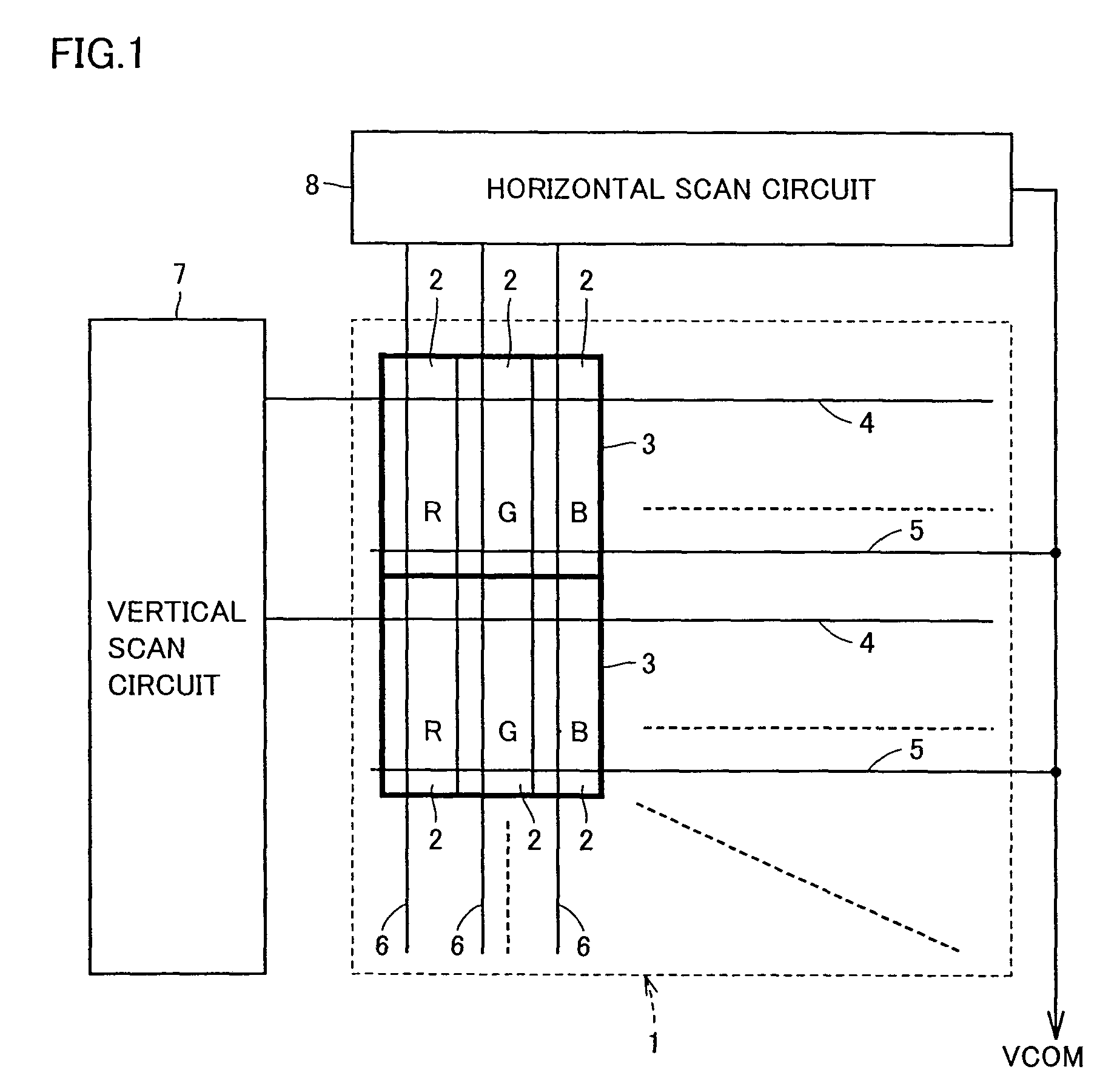
[0023]FIG. 1 is a block diagram showing the configuration of a color liquid crystal display device according to a first embodiment of the present invention. In FIG. 1, this color liquid crystal display device includes a liquid crystal panel 1, a vertical scan circuit 7 and a horizontal scan circuit 8. The color liquid crystal display device is provided in, for example, a cellular phone.
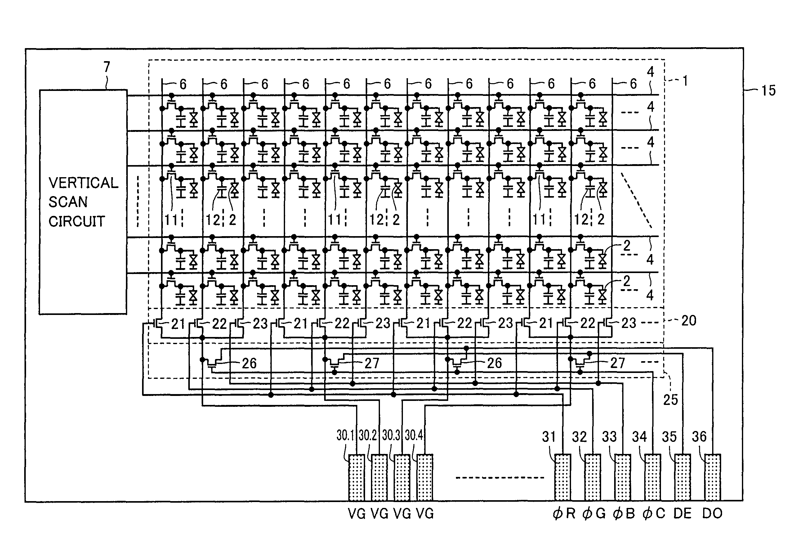
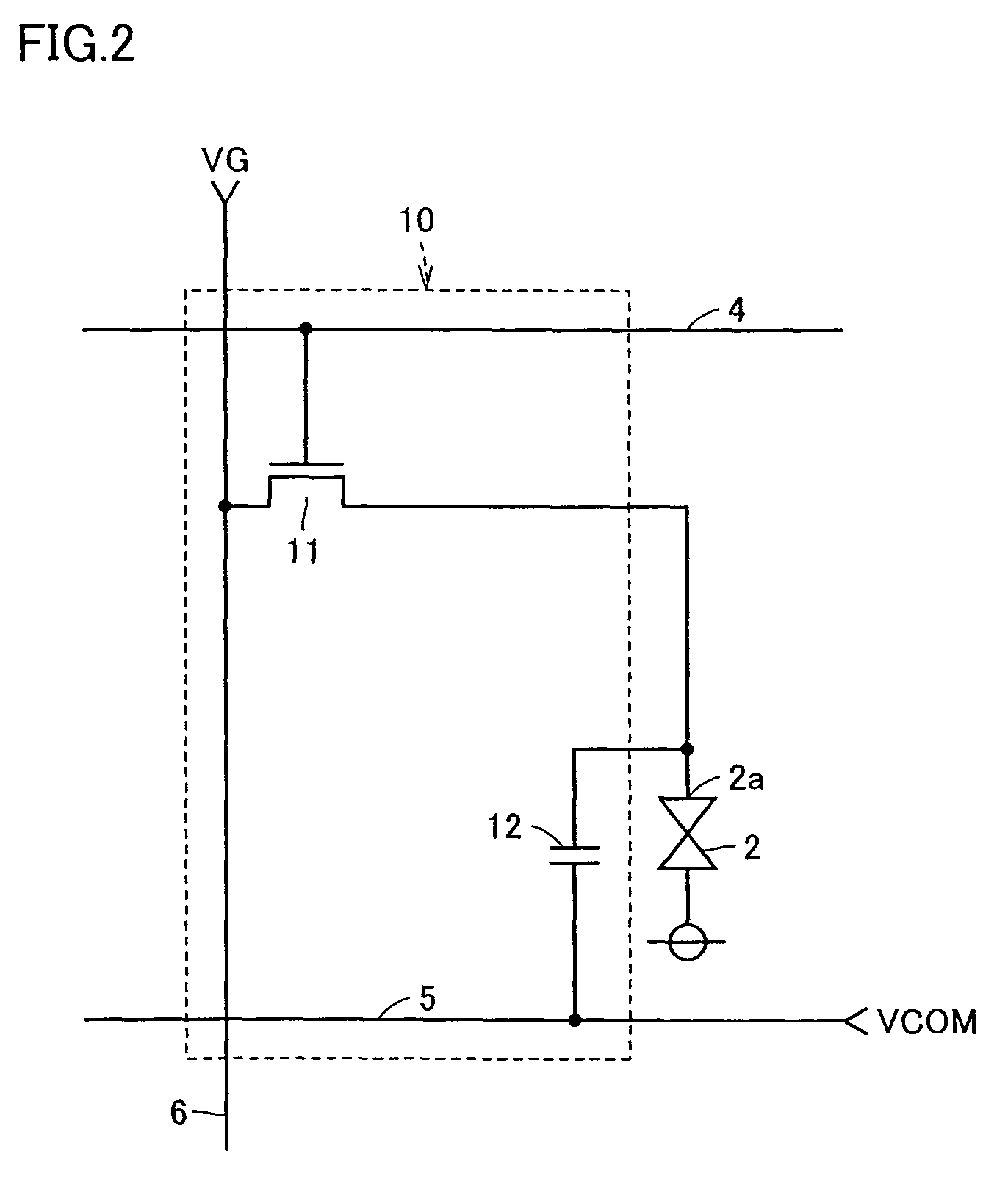
[0024]Liquid crystal panel 1 includes: a plurality of liquid crystal cells 2 arranged in a plurality of rows and columns; a plurality of scan lines 4 provided in correspondence with the plurality of rows, respectively; a plurality of common potential lines 5 provided in correspondence with the plurality of rows, respectively; and a plurality of data lines 6 provided in correspondence with the plurality of columns, respectively. The plurality of common potential lines 5 are connected to one another.
[0025]Liquid crystal cells 2 are divided into a plurality of groups in each row in advance. Each group ha...
second embodiment
[0047]FIG. 7 illustrates a method for inspecting an LCD module according to a second embodiment of the present invention. In FIG. 7, a plurality of (three in FIG. 7) LCD modules 41 to 43 are formed on the surface of a glass substrate 40 for inspection method in the second embodiment. Each of LCD modules 41 to 43 is equal in configuration to that shown in FIG. 3. Terminals 31 to 36 used when inspecting each of LCD modules 41 to 43 are arranged to be opposed to one side of glass substrate 40. In addition, an R terminal 51, a G terminal 52, a B terminal 53, control terminals 54 to 56, an even-numbered data terminal 57 and an odd-numbered data terminal 58 are arranged along the one side of glass substrate 40.
[0048]R terminals 31 of LCD modules 41 to 43 are all connected to R terminal 51. G terminals 32 of LCD modules 41 to 43 are all connected to G terminal 52. B terminals 33 of LCD modules 41 to 43 are all connected to B terminal 53. Control terminals 34 of LCD modules 41 to 43 are all...
third embodiment
[0052]FIG. 8 illustrates a method for inspecting an LCD module according to a third embodiment of the present invention. In FIG. 8, a plurality of (three in FIG. 8) LCD modules 61 to 63 are formed on the surface of a glass substrate 60 for the inspection method in the third embodiment. External terminal sections 61a to 63c of LCD modules 61 to 63 are arranged to be opposed to one side of glass substrate 60. Inspection terminal switch circuits 64 to 66 are provided along external terminal sections 61a to 63c of LCD modules 61 to 63, respectively. In addition, an R terminal 71, a G terminal 72, a B terminal 73, control terminals 74 to 76, an even-numbered data terminal 77, and an odd-numbered data terminal 78 are disposed along the one side of glass substrate 60.
[0053]FIG. 9 is a circuit block diagram showing the configuration of LCD module 61. FIG. 9 is given to be compared with FIG. 3. Referring to FIG. 9, LCD module 61 differs from LCD module shown in FIG. 3 in that inspection term...
PUM
 Abstract
Description
Claims
Application Information