Voltage controlled oscillator for reducing gain surge

A voltage-controlled oscillator and resonant circuit technology, applied in power oscillators, electrical components, etc., can solve the problem of no voltage-controlled oscillator and so on

Active Publication Date: 2008-04-23
PEKING UNIV +1
View PDF4 Cites 0 Cited by
  • Summary
  • Abstract
  • Description
  • Claims
  • Application Information

AI Technical Summary

Problems solved by technology

And an effective solution is to reduce the K when designing the VCO VCO fluctuations, but there is currently no voltage-controlled oscillator of this type

Method used


Image

  • Voltage controlled oscillator for reducing gain surge
  • Voltage controlled oscillator for reducing gain surge
  • Voltage controlled oscillator for reducing gain surge

Examples


Embodiment Construction

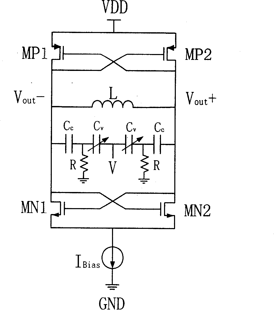
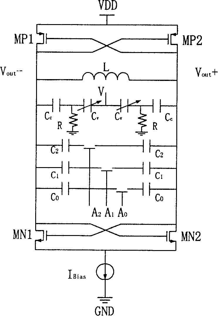
[0020] Such as Figure 5 As shown, the present invention is figure 2 Improved on the basis of the medium voltage controlled oscillator circuit, the present invention uses the coupling capacitor C in the LC resonant circuit c Change into the form of switch coupling capacitor array. Switch coupling capacitor ( Figure 5 Cc0, Cc1 and Cc2) and the switch coarse adjustment capacitance (ie C in the figure 2 , C 1 And C 0 ) Synchronous control is implemented by the chip. Switch coarse adjustment capacitor through digital control bit A 2 A 1 A 0 To turn on or off the switch to determine whether the capacitor is connected to the LC tank. When A 2 A 1 A 0 With different digital levels, the capacitors in the switched capacitor array will be connected to the LC resonant tank of the oscillator in different combinations, so that the total equivalent capacitance C is changed.

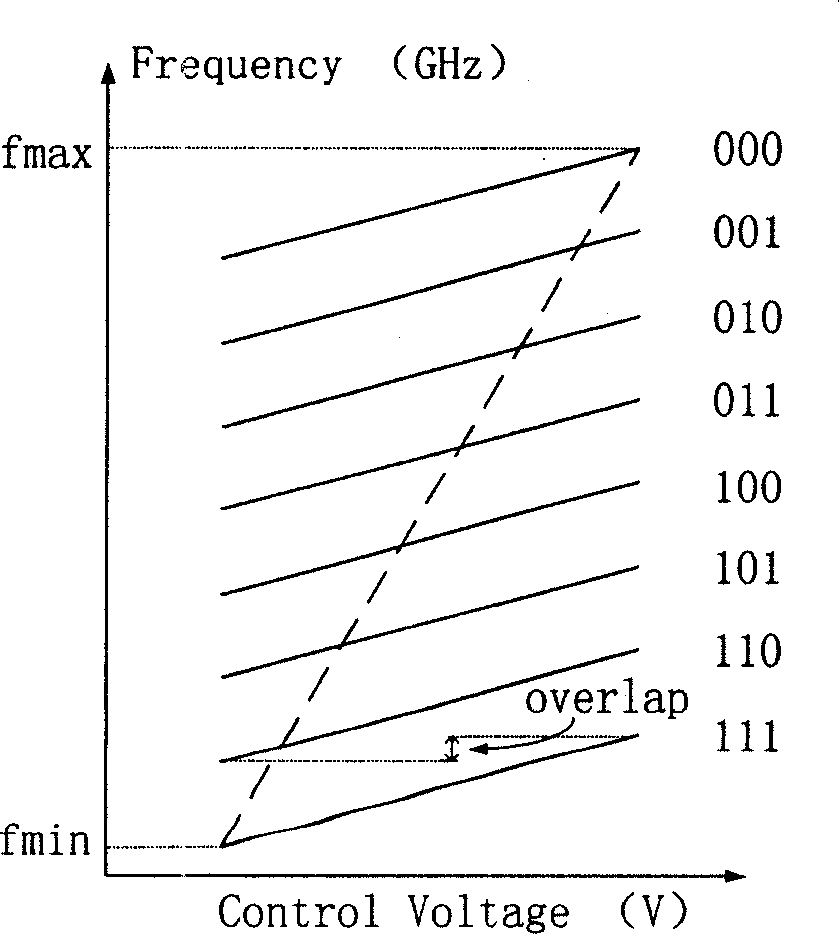
[0021] by Figure 4 The frequency modulation curve shown shows that the curve close to the bottom corresponds to C swi...


PUM


Abstract

The invention consists of LC resonance loop used in providing negative conductance active device. The capacitor of the above LC resonance loop is a varactor capacitor connected in series with a coupling capacitor, and then connected in parallel with a digital controlled switching capacitor. The above coupling capacitor is also a digital controlled switching capacitor.

Description

Technical field [0001] The invention relates to a voltage-controlled oscillator, in particular to a voltage-controlled oscillator with small gain fluctuations. Background technique [0002] In the past decade or so, personal wireless communication systems such as pagers, cordless phones, analog and digital cellular phones, as well as digital TV and broadcasting have developed rapidly, and wireless communication has become the most important industry after the PC industry. Because integrated circuits have the characteristics of small size, low power consumption, and low cost, the rapid development of wireless communication technology has led to the rapid development of radio frequency integrated circuits. Currently, radio frequency integrated circuits have become one of the important research areas of microelectronics. Designing and researching high-performance key circuit modules has become a vital driving force for the advancement of radio frequency integrated circuit technology...

Claims


Application Information

Patent Timeline
Patent Type & Authority Patents(China)
IPC IPC(8): H03B5/12
Inventor 石浩张国艳廖怀林黄如张兴王阳元
Owner PEKING UNIV
Why Eureka
Try Eureka