
Branch pipe of horn loudspeaker and dispersion characteristic controlling method

A loudspeaker and horn-shaped technology, applied in the field of horn-shaped loudspeaker systems, can solve the problems of inconsistent horn length and increased distortion.

Inactive Publication Date: 2008-06-11
MEYER SOUND LABORATORIES
View PDF6 Cites 0 Cited by
  • Summary
  • Abstract
  • Description
  • Claims
  • Application Information

AI Technical Summary

Problems solved by technology

In general, highly directional horns can be achieved with long, slow, enlarged horns, but, despite this, the dispersion of the horns only has an upper limit of about 20 degrees
The length of such a long horn does not meet people's requirements, because the distortion produced by the horn increases with the increase of the number of wavelengths of the sound pressure wave in the horn

Method used


Image

  • Branch pipe of horn loudspeaker and dispersion characteristic controlling method
  • Branch pipe of horn loudspeaker and dispersion characteristic controlling method
  • Branch pipe of horn loudspeaker and dispersion characteristic controlling method

Examples


Embodiment Construction

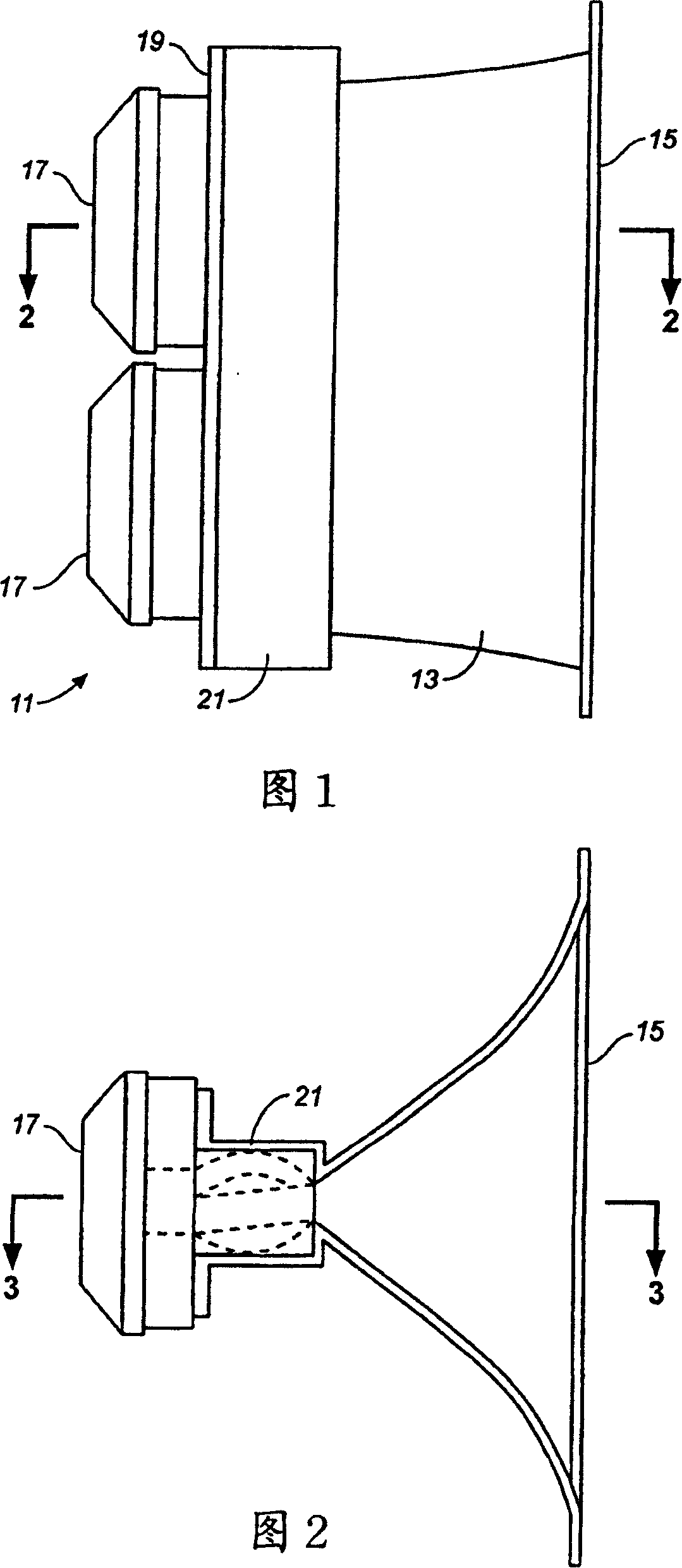
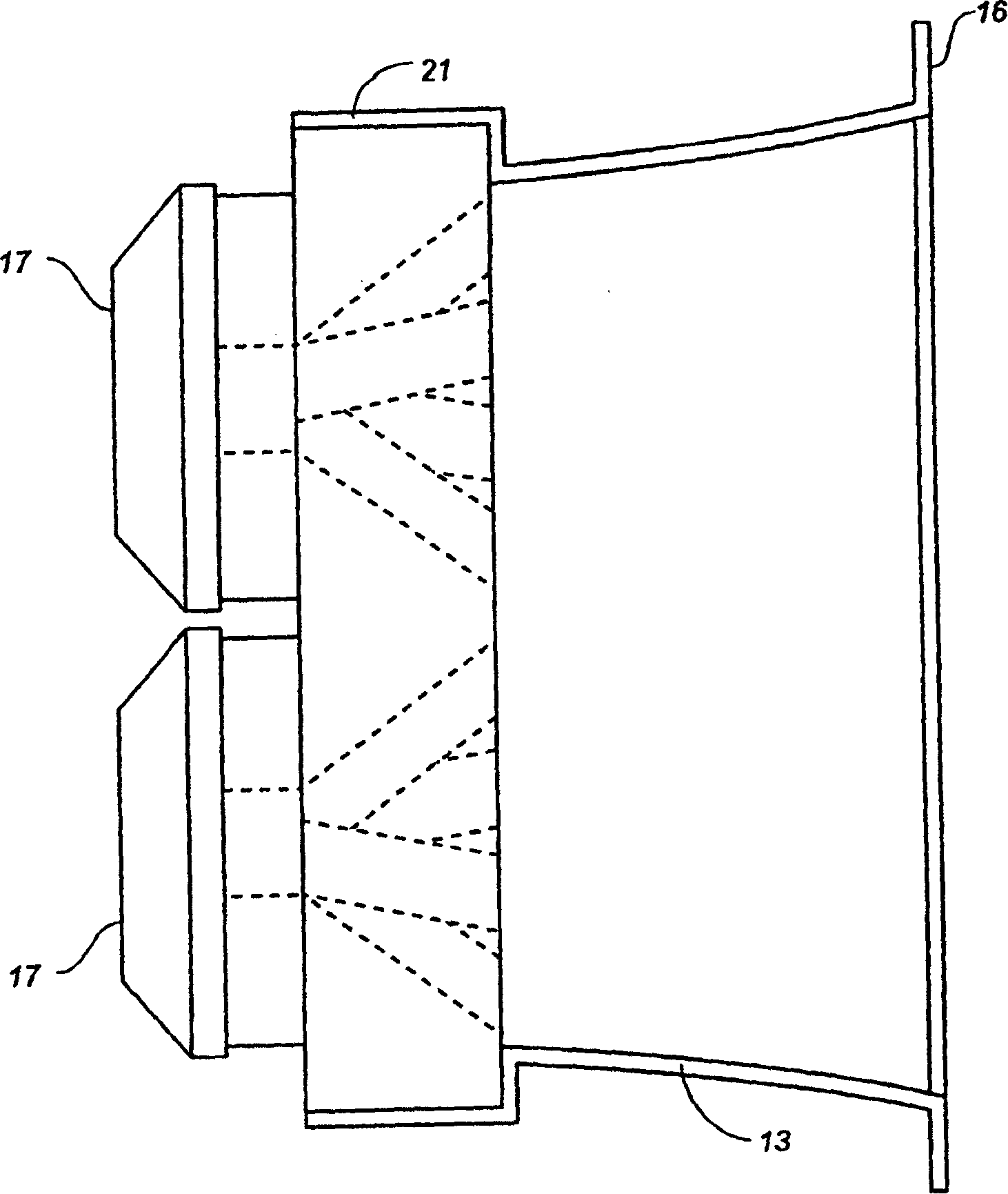
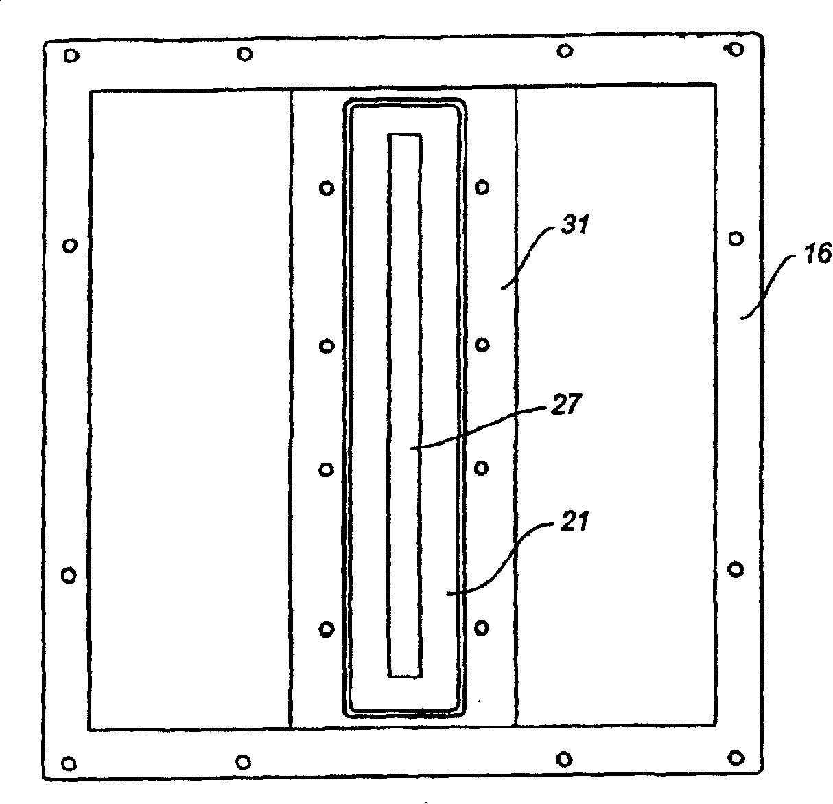
[0042] Referring to FIGS. 1-3 , a horn-shaped speaker system 11 includes a horn 13 having an mouth end 15 and two compression drivers 17 spaced apart and closely disposed on a rear end 19 of the horn. The rear end of the horn has an enlarged manifold mounting cavity 21 for holding a drive manifold which will be described below. The arrangement of the drive manifold in the mounting cavity 21 is shown in Figure 2 and image 3 In , the manifold indicated by the dotted line in the figure represents the acoustic power waveguide of the two driven manifolds that will be described below.

[0043] The design of the horn for the horn-shaped speaker system shown in Figures 1-3 is further shown in Figure 4-5 middle. It can be seen from these figures that the generally square horn mouth 15 has a peripheral mounting flange 16 for mounting the horn on a loudspeaker stand. from Figure 5 As can be seen better, the flared vertical sidewall 25 extends inwardly to form an elongated throat 27 e...


PUM


Abstract

A manifold (81) for a horn loudspeaker has an input end having at least one input port for receiving acoustic power from at least one acoustic driver, and an output end for delivering acoustic power to the throat opening of the horn. The output end of the manifold has at least two and suitably multiple output ports. An acoustic power waveguide is provided for each output port and connects each of the output ports to the input port of the manifold. Acoustic power received by the input port is divided between the acoustic waveguide such that it is delivered to the aligned output ports to simulate a line array of acoustic power sources.

Description

technical field [0001] The present invention relates generally to a horn-shaped loudspeaker system and, more particularly, to a manifold for coupling one or more acoustic drivers to a loudspeaker horn. The present invention also relates to improvements in the horn and horn manifolds of horn loudspeaker systems by improving the directional characteristics of the loudspeaker without introducing large distortions. The invention is particularly advantageous for arraying horn-shaped loudspeaker systems to achieve desired acoustic coverage while avoiding undesired interaction between individual horns. Background technique [0002] In order to optimize the horn-shaped loudspeaker system array, people often hope to control the scattering characteristics of the horn, so that the scattering in the array direction is narrowed and the scattering perpendicular to the array direction is broadened. Thus, in the case of vertically stacked horn loudspeakers, one always seeks to minimize the...

Claims


Application Information

Patent Timeline
Patent Type & Authority Patents(China)
IPC IPC(8): G10K11/22H04R1/28G10K11/02G10K11/28H04R1/30H04R1/34
CPCG10K11/22H04R1/345G10K11/025G10K11/28H04R1/30
Inventor J·D·迈耶P·迈耶R·D·赫尔
Owner MEYER SOUND LABORATORIES
Learn More