Honeycomb type heat accumulation body composite pouring die and manufacturing method of the heat accumulation body

A manufacturing method and heat accumulator technology, applied in the manufacture of tools, molds, ceramic molding machines, etc., can solve the problems of long time occupation of steel molds, low turnover rate of steel molds, and inconvenient manufacturing, so as to reduce production costs and improve production costs. Effects on labor productivity and ease of manufacture

Inactive Publication Date: 2008-08-13
朱金良
View PDF3 Cites 0 Cited by
  • Summary
  • Abstract
  • Description
  • Claims
  • Application Information

AI Technical Summary

Problems solved by technology

In the above manufacturing method, since the pouring body needs to be maintained in the steel mold, it takes a long time to occupy the steel mold, the turnover rate of the steel mold is low, and the manufacturing cost is increased. In addition, the mold cores are densely distributed, and the demoulding core is troublesome, which not only saves time It is long and easy to damage the cast body that has just been poured, which is not convenient enough for manufacturing

Method used


Image

  • Honeycomb type heat accumulation body composite pouring die and manufacturing method of the heat accumulation body

Examples


Embodiment 1

[0022] (embodiment 1, composite casting mold)

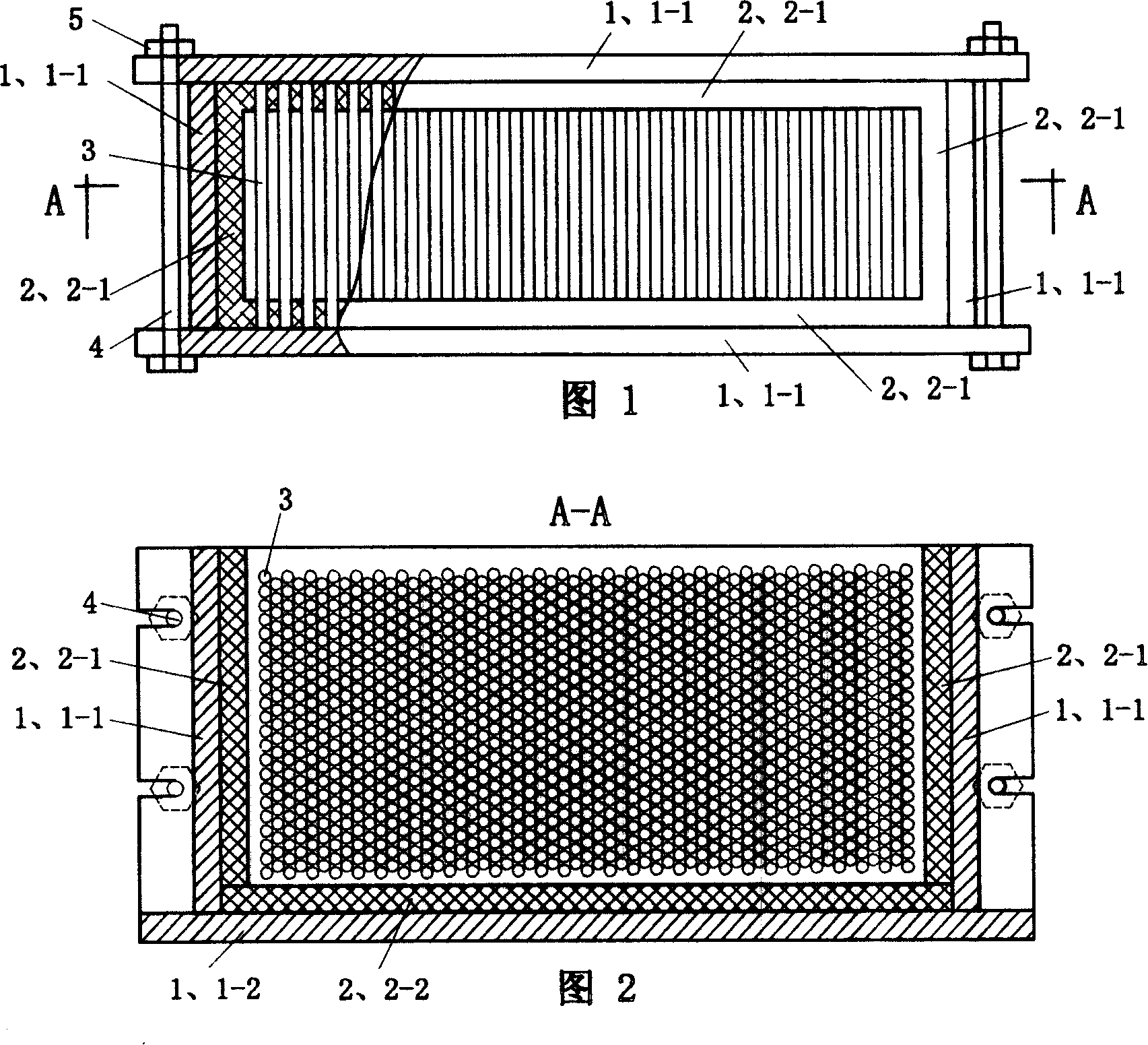
[0023] Embodiment 1 shown in the accompanying drawings has a steel mold 1, and the steel mold 1 is formed by detachably connecting a bottom plate 1-1 and four side plates 1-2. The detachable connection adopts that four side plates 1-2 are connected on the bottom plate 1-1 by mortise, and bolts 4 are connected between two pairs of sides, and are fastened by nuts 5 . The steel mold 1 is provided with a matching combustible inner mold 2, and the combustible inner mold 2 is also composed of a bottom plate 2-1 and four side plates 2-2, and between the four side plates 2-2 and the bottom plate 2-1 and adjacent sides The boards are bonded together. The materials for making the combustible inner mold 2 and the combustible mold core 2-3 can be plastics and / or rubber and / or wood. The base plate 2-1 and the four side plates 2-2 of the combustible inner mold 2 can be made of a unified material, or can be made of different materials. The m...

Embodiment 2

[0024] (embodiment 2, composite casting mold)

[0025] Two of the four side plates of the combustible inner mold 2 of embodiment 2 are provided with core holes 2-2-1 made of rubber, the other two side plates are made of plastic, and the bottom plate 1-1 is made of wood , all the other are identical with embodiment 1.

Embodiment 3

[0026] (embodiment 3, honeycomb heat accumulator manufacturing method,)

[0027] The raw material formula of Example 3 generally takes 40-60 parts of aggregate by weight; 30-50 parts of base material; 7-12 parts of binder; and 0.06-1.3 parts of water reducing agent. The above-mentioned aggregate adopts corundum particles, high-alumina bauxite particles, mullite particles or cordierite particles; Calcium aluminate cement and high-temperature alumina micropowder or silica fume; the above-mentioned water reducer uses sodium tripolyphosphate or sodium hexametaphosphate. In this example, 50 parts of mullite particles are used as the aggregate, 40 parts of sintered mullite powder are used as the base material, 5 parts of pure calcium aluminate cement and 5 parts of high-temperature alumina micropowder are used as the binder, and tripolyphosphoric acid is used as the water reducing agent. Sodium 1 part. Accurately weigh the above raw materials into the conical double-screw mixer ac...


PUM


Abstract

The invention relates to a comb heat-storage complex pouring mode. It has ingot mode which is formed by detachably-connecting end plate and four side plates; the matching inflammable inner mode is formed by fix-connecting end plate and four side plates and is arranged inside pouring mode; mode core holes are separately distributed on the two opposed said plates of inflammable inner mode; inflammable mode cores are separately inserted into the two opposed mode core holes. Adopting the said comb heat-storage complex pouring mode to make comb heat-storage can cure pouring object at inner mode.

Description

technical field [0001] The invention relates to a pouring mold for a honeycomb heat storage body and a manufacturing method for the honeycomb heat storage body. Background technique [0002] At present, the common honeycomb heat storage body is in the shape of cuboid, cube or cylinder, and there are parallel passages running through the two opposite surfaces inside. Usually the raw material ratio of the honeycomb heat storage body is as follows (by weight): 40-60 parts of aggregate; 30-50 parts of matrix material; 7-12 parts of binder; 0.06-1.3 parts of water reducing agent. The above-mentioned aggregate adopts corundum particles, high-alumina bauxite particles, mullite particles or cordierite particles; Calcium aluminate cement and high-temperature alumina micropowder or silica fume; the above-mentioned water reducer uses sodium tripolyphosphate or sodium hexametaphosphate. At present, the casting mold for manufacturing honeycomb heat storage body by casting method is a s...

Claims


Application Information

Patent Timeline
Patent Type & Authority Patents(China)
IPC IPC(8): B28B7/18B28B13/00B28B1/00B28B11/00
Inventor 朱金良章焕明陈文龙高义
Owner 朱金良
Why Eureka
Try Eureka