
Rear projection screen

A transmissive screen technology, applied in television, optics, instruments, etc., can solve problems such as small focal length, uneven color of the transmissive screen 10, and increased difference in the angle of light emission of three-color images.

Inactive Publication Date: 2008-08-27
DAI NIPPON PRINTING CO LTD
View PDF13 Cites 1 Cited by
  • Summary
  • Abstract
  • Description
  • Claims
  • Application Information

AI Technical Summary

Problems solved by technology

[0009] However, in such a transmissive screen 10, when the focal length of the Fresnel lens constituting the transmissive screen 10 is shortened, in the image source 20, the difference in the emission angles of the three-color image lights projected for each position increases.
Here, if the difference in the emission angle with respect to the vertical direction in which the diffusion angle of the transmission type screen 10 is narrow increases, color unevenness is easily generated on the transmission type screen 10
Therefore, considering the occurrence of color unevenness, it is difficult to make the focal length of the viewing side of the transmissive screen 10 less than 10 m, and it is impossible to reduce the speckle phenomenon without causing color unevenness.

Method used


Image

  • Rear projection screen
  • Rear projection screen
  • Rear projection screen

Examples


Embodiment

[0046] next to Figure 1~3 Specific examples of the illustrated implementation forms are described.

no. 1 Embodiment

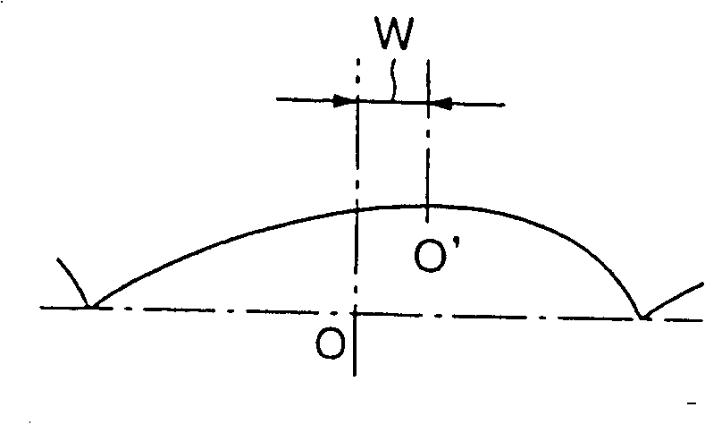
[0048] The first embodiment refers to the following example, that is, in figure 1 In the embodiment shown, the top of the lens arranged in the convex lens at the top and bottom of the outer edge of the screen surface can deviate from the central position of the convex lens along the direction of the center of the screen surface, and the outer edge of the screen surface The direction of diffusion of the top end and the bottom end of the portion may be inclined toward the central portion of the screen surface.

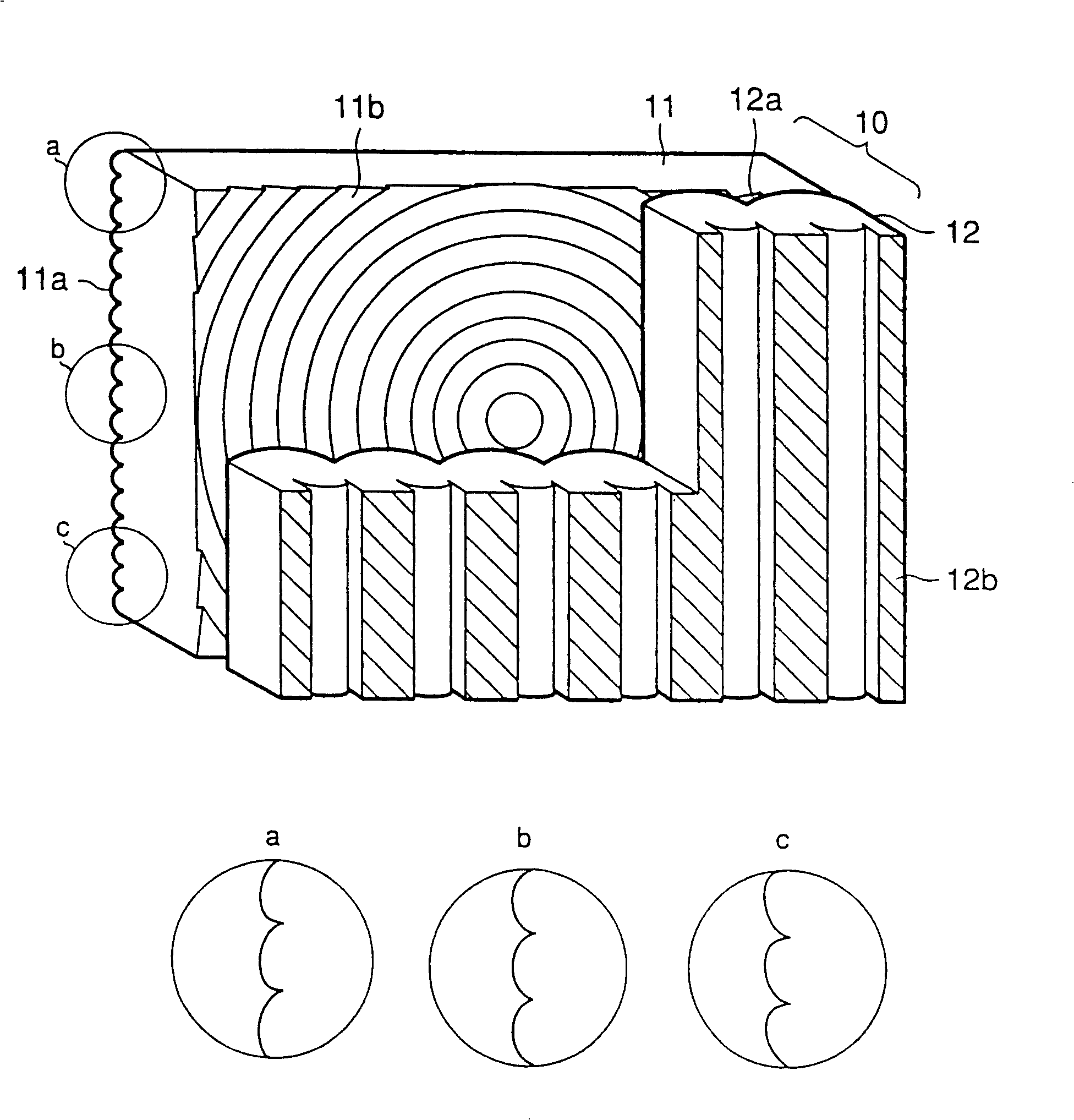
[0049] In this embodiment, as a transmissive screen for a 60" (inch) rear projection TV set, a figure 1 A transmissive screen 10 is shown. In addition, in the Fresnel lens 11, the lenticular lens 11a for vertical diffusion is formed on the light incident side, and the circular Fresnel lens 11b is formed on the light exit side.

[0050] Here, the mold 32 for forming the lenticular lens 11a for vertical diffusion uses a cutter 31 having a cross-sectional shape in which...

no. 2 Embodiment

[0063] The 2nd embodiment is the following embodiment, and this embodiment refers to figure 1 In the embodiment shown, the lens top of the convex lens that is arranged on the top end and the bottom end of the outer edge of the screen surface can deviate from the central position of the convex lens along the end direction of the screen surface, as the outer edge of the screen surface. The diffusion directions of the top end and the bottom end are inclined toward the end of the screen surface. The basic structure of this embodiment is the same as that of the above-mentioned first embodiment.

[0064] In this case, since the lens shape is the same, only the deviation direction of the top of the lens is different, so the diffusion characteristic diagram of the top, center, and bottom of the biconvex lens for vertical diffusion is opposite to that of the first example. They are shown in Fig. The states shown in 9, 8 and 7.

[0065] When measuring the transmissive screen 10 at the...


PUM


Abstract

A rear projection screen 10 comprises a Fresnel lens sheet 11 arranged on the projection side, and a lenticular lens sheet 12 arranged on the observation side. The Fresnel lens sheet 11 has a lenticular lens 11a for vertical diffusion on its light-entering side. The lenticular lens 11a for vertical diffusion contains a plurality of convex lenses which extend horizontally, and these plural convex lenses are arranged with a constant pitch. Further, the diffusion angle of the lenticular lens 11a for vertical diffusion continuously increases, and, at the same time, the direction of diffusion is gradually inclined to the central part side as the distance from the central part toward the edge side on the screen surface increases. The diffusion properties (the angle and direction of diffusion) of the lenticular lens 11a thus continuously vary between the central part and edge of the screen surface.

Description

technical field [0001] The present invention relates to a transmissive screen comprising a Fresnel lens and a lenticular lens. Background technique [0002] In the past, as a transmissive screen used in a rear projection type television, etc., there are known forms including a Fresnel lens that refracts projected light emitted from an image source to form substantially parallel light, and A lenticular lens that scatters projected light and forms an image. [0003] In addition, among such existing transmissive screens, for example, a form is known in which projected light is diffused in the horizontal direction by a lenticular lens sheet for horizontal diffusion, and the projection light is diffused by a diffusing agent and a lenticular lens sheet for vertical diffusion. The projected light is diffused in the vertical direction. Also, in these lenticular lens sheets, generally, the divergence angle remains the same over the entire screen surface. [0004] However, in such ...

Claims


Application Information

Patent Timeline
Patent Type & Authority Patents(China)
IPC IPC(8): G03B21/60H04N5/72G03B21/62G03B21/625H04N5/74
CPCG03B21/625H04N5/74
Inventor 高桥由树后藤正浩渡边一十六本田诚织田训平高桥克则
Owner DAI NIPPON PRINTING CO LTD
Learn More