

Electromagnetic valve device
A technology of solenoid valve and moving core, which is applied in the direction of valve device, valve operation/release device, lifting valve, etc., to achieve the effect of reducing the number of components and reducing the cost
- Summary
- Abstract
- Description
- Claims
- Application Information
AI Technical Summary
Problems solved by technology
Method used
Image

Examples
no. 1 example
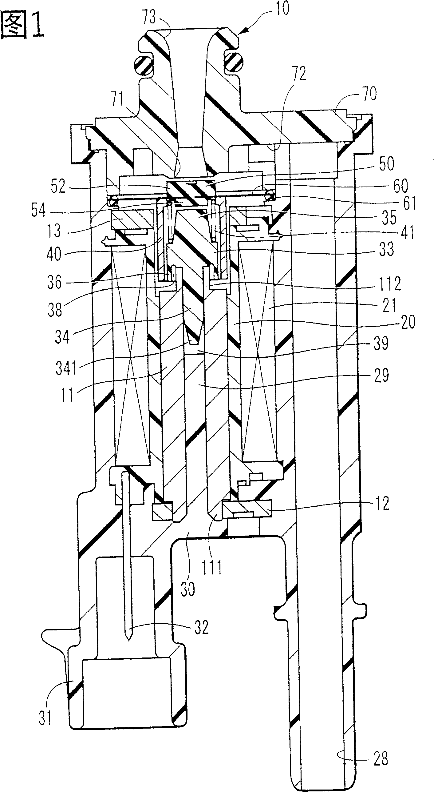
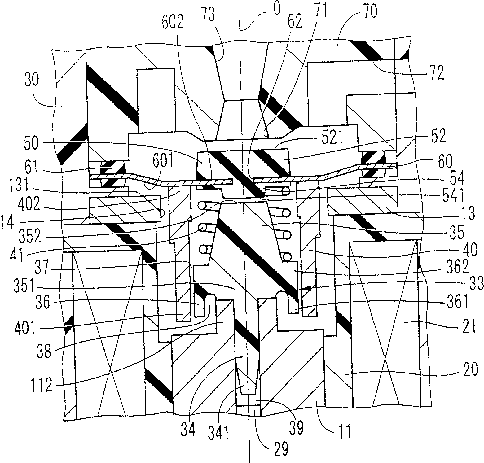
[0032] 1 and 2 show a solenoid valve device according to one embodiment of the present invention. The solenoid valve device 10 of this first embodiment is used in a system for delivering, for example, evaporated fuel generated in a fuel tank of a vehicle to an engine. The solenoid valve device 10 is used to open and close the flow path of evaporated fuel.
[0033] The passage member 70 is made of resin, and includes a valve seat 71 and an inflow passage 72 and an outflow passage 73 as fluid passages. The valve seat 71 is provided between the downstream end of the inflow passage 72 and the upstream end of the outflow passage 73 so that the valve element 50 can be seated thereon. When the valve element 50 is seated on the valve seat 71, blocking the communication between the downstream portion of the inflow passage 72 and the upstream portion of the outflow passage 73 blocks the fluid passage. When the valve element 50 rises from the valve seat 71, the downstream portion of th...
no. 2 example
[0063] Figure 5 Showing a solenoid valve device according to a second embodiment of the present invention, the same elements as those of the first embodiment are denoted by the same reference numerals.
[0064] In the solenoid valve device 80 of the second embodiment, the movable core end 401 of the movable core 40 opposed to the fixed core 11 is formed to have a smaller diameter than the other end 402 . A stepped portion 403 is formed on the peripheral side wall. Also instead of the small diameter portion 112 of the first embodiment, a cylindrical stopper portion 113 surrounding the outer peripheral side wall of the end 401 of the movable core 40 is provided coaxially with the end of the fixed core 11 which is positioned at the solenoid valve. The device 80 faces the movable core 40 inside. In addition, in the solenoid valve device 80, the space 38 having a circular cross section is formed by the fixed core side end 361 of the guide wall 36 and the base end 351 of the adju...
no. 3 example
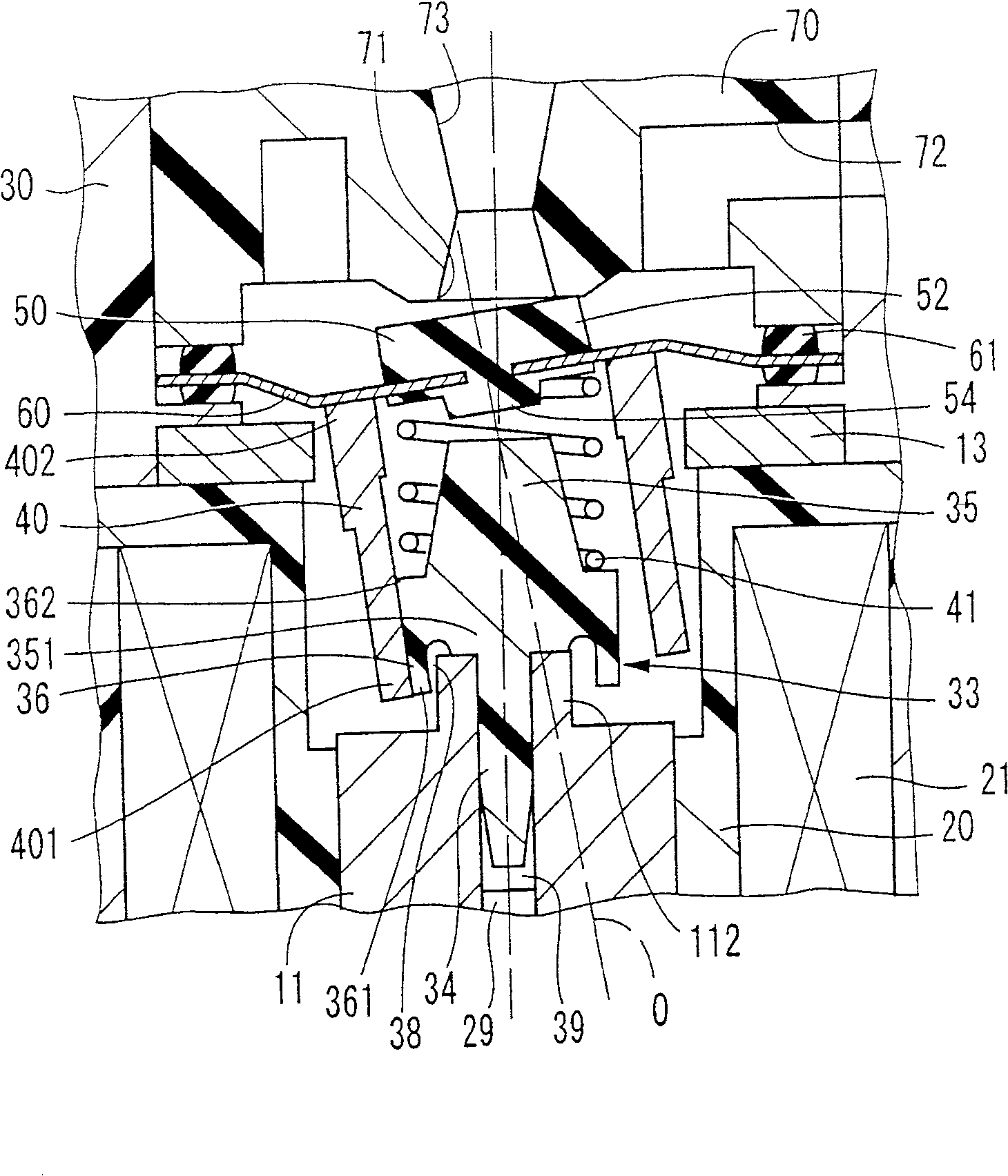
[0070] Figure 6 A solenoid valve device according to a third embodiment of the present invention is shown. The same elements as those of the first and second embodiments are denoted by the same reference numerals.
[0071] The solenoid valve device 85 of the third embodiment differs from the solenoid valve device of the second embodiment in the structure of the guide wall of the guide member 33 .
[0072] The guide wall 86 of the third embodiment is formed in a cylindrical shape that continuously surrounds the peripheral side wall, that is, radially surrounds the outer side of the movable core 40 . The guide wall 86 is arranged coaxially with the movable core 40 in its normal position, thereby creating a very small gap 87 with the end 401 , which has a smaller diameter than the rest of the movable core 40 . With this structure, the guide wall 86 can guide the end portion 401 of the movable core 40 from the radially outer side to the central axis O direction. In the guide w...
PUM
 Abstract
Description
Claims
Application Information