Imaging lens

A camera lens, lens technology, applied in the direction of lenses, optics, instruments, etc., can solve the problems of damage to information equipment, difficult to realize, and difficult to miniaturize information equipment.

Inactive Publication Date: 2008-09-10
SONY CORP
View PDF14 Cites 0 Cited by
  • Summary
  • Abstract
  • Description
  • Claims
  • Application Information

AI Technical Summary

Problems solved by technology

[0008] For the imaging lens disclosed in Japanese Patent Application Laid-Open No. 2002-55278, the overall length is too long when built in information equipment, and when changing the optical power, the first lens group is moved, which leads to complicated mechanical design, and difficult to achieve low cost
In such an imaging lens, since the lens group close to the object to be captured is moved and the lens holder is pulled out from the main device body for zooming, there is a fear that the information device may be damaged by falling, colliding or bumping into other objects
[0009] On the other hand, even the imaging lens disclosed in Japanese Patent Application Laid-Open No. 2002-72095 is ideal in terms of collision avoidance from the viewpoint of fixing the lens group close to the object to be captured when the power is changed. Yes, since the last lens group is positive, it is difficult to reduce the back focus, which makes it difficult to miniaturize information equipment

Method used


Image

  • Imaging lens
  • Imaging lens
  • Imaging lens

Examples


no. 1 approach

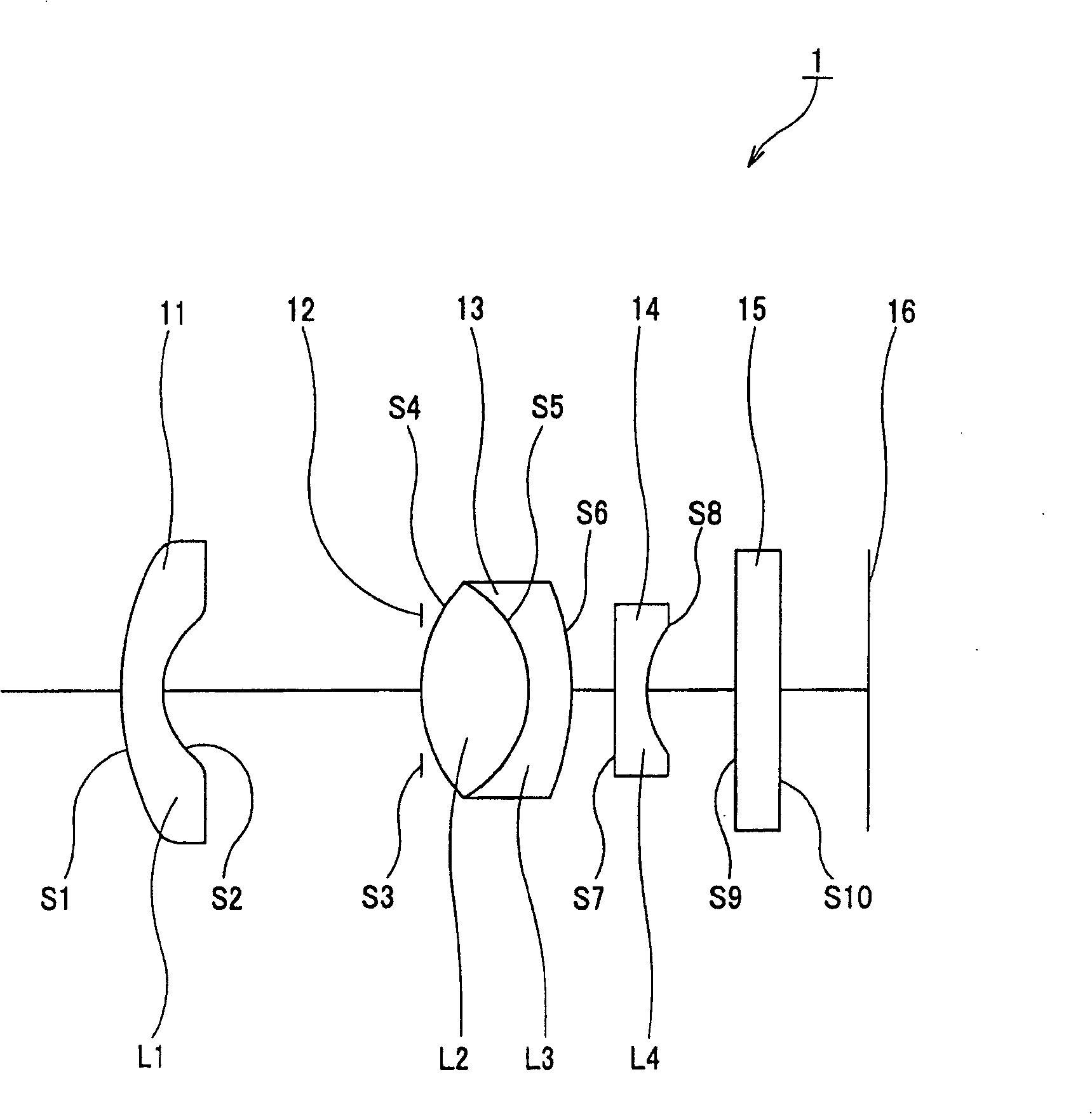
[0047] Below, combine Figure 1 to Figure 3 , the imaging lens 1 as the first embodiment of the present invention is explained.

[0048] Such as Figure 1 to Figure 3As shown, the imaging lens 1 includes: a first lens group 11 with negative refractive power, a diaphragm 12, a second lens group 13 with positive refractive power, and a third lens group 14 with negative refractive power. One side is configured sequentially.

[0049] The imaging lens 1 guides light into the first lens group 11, passes through the aperture 12, the second lens group 13 and the third lens group 14 in turn, and passes through the optical filter 15 to be described later, and gathers the light in the first lens group configured in the image. On the imaging plane of the imaging device 16 on the side. The imaging device 16 may be a CCD for converting light collected by the imaging lens 1 into an electronic signal and outputting the electronic signal thus generated.

[0050] Specifically, the first len...

no. 2 approach

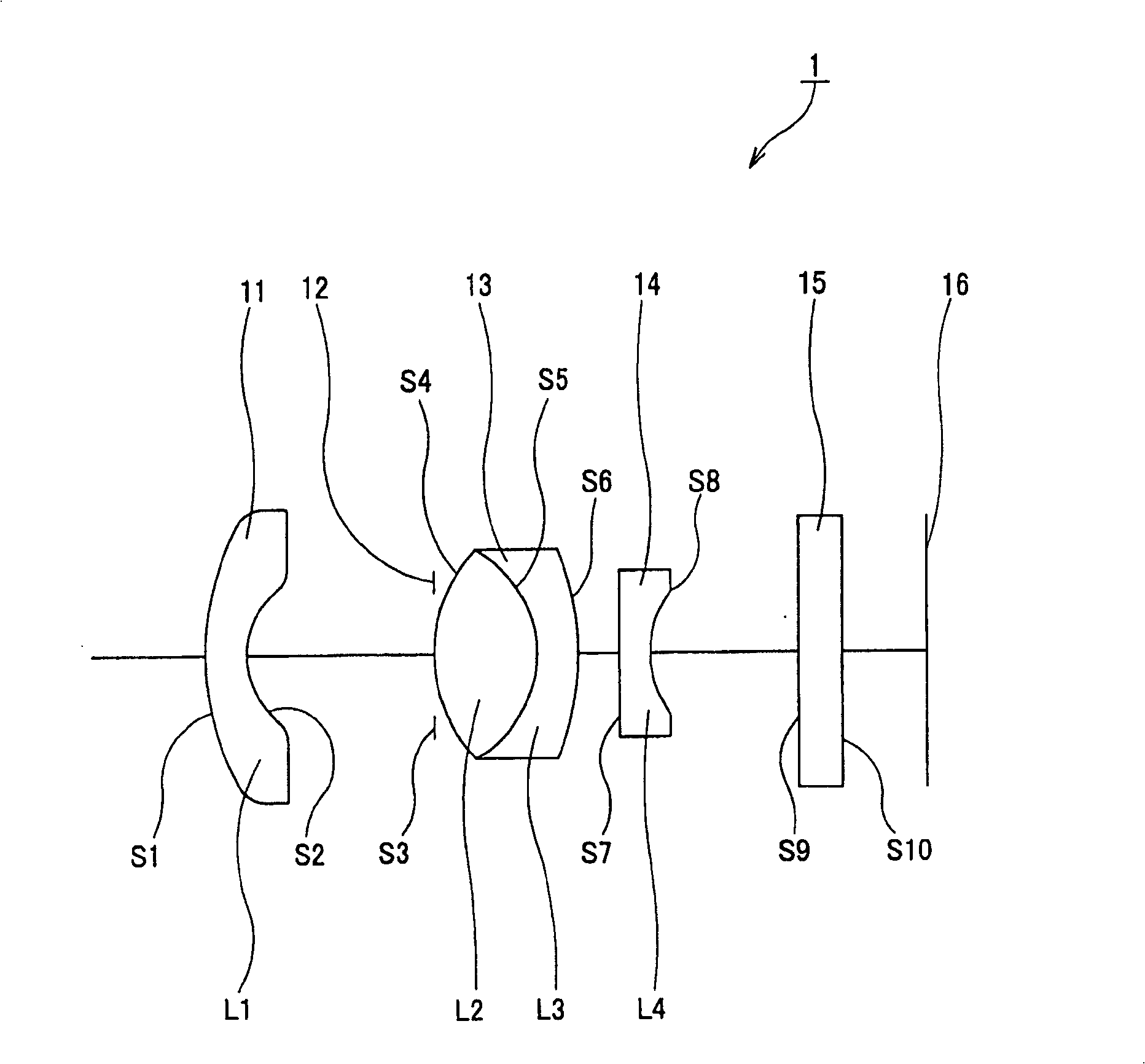
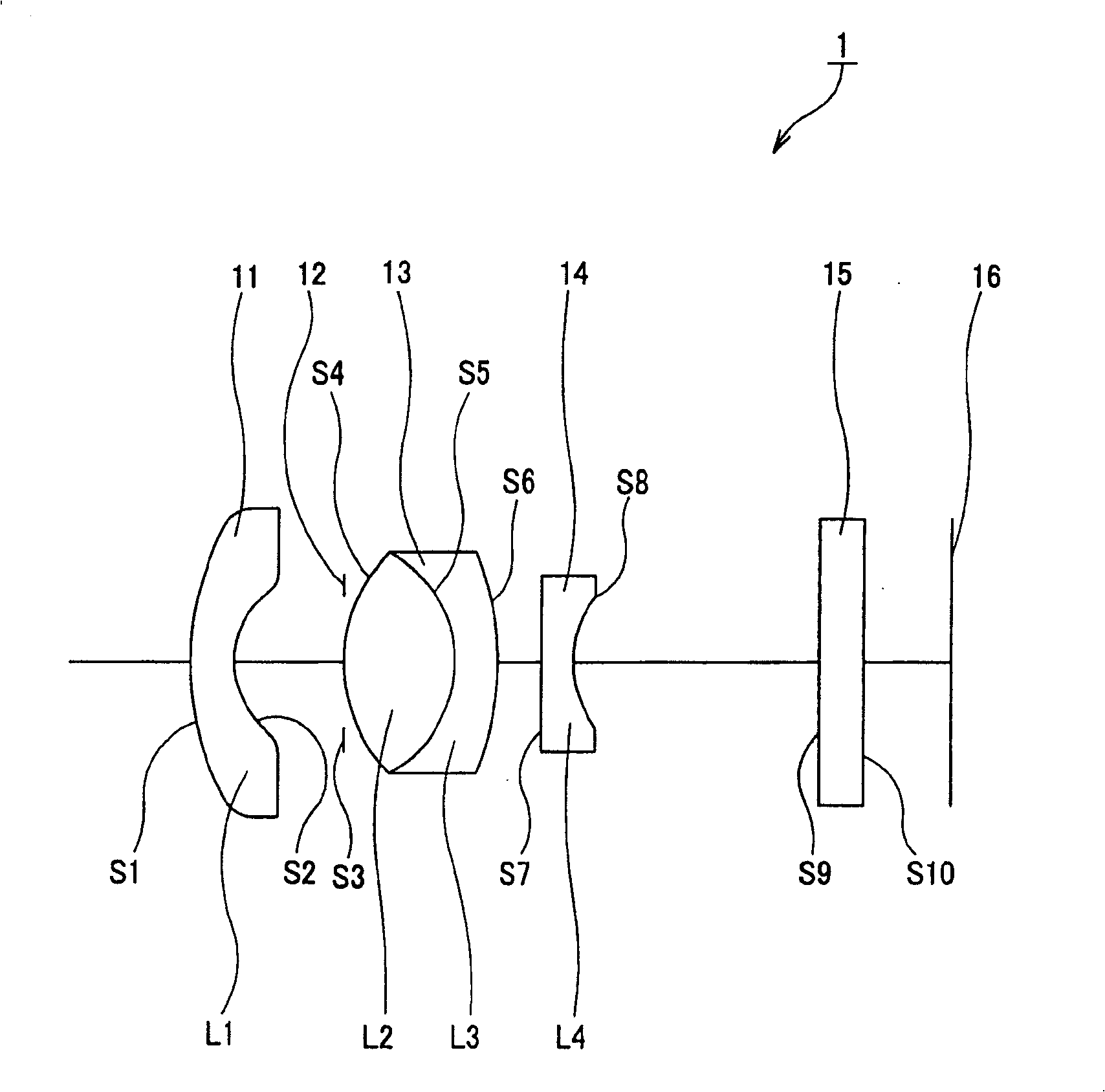
[0099] Below, combine Figure 13 to Figure 15 A second embodiment using the imaging lens of the present invention is explained.

[0100] In the following explanation, similar parts or components to those of the imaging lens 1 in the first embodiment are denoted by the same reference numerals, and detailed explanations are omitted, and only differences between parameters of the respective lenses are explained.

[0101] Similar to the imaging lens 1 of the first embodiment, the imaging lens 2 of the second embodiment can change its power by moving the second lens group 13 along the optical axis. and Figure 1 to Figure 3 resemblance, Figure 13 shows the lens arrangement in which the second lens group 13 is positioned at the wide-angle end, Figure 15 shows the lens arrangement in which the second lens group 13 is positioned at the telephoto end, Figure 14 Each lens arrangement in which the second lens group 13 is positioned between the wide-angle end and the telephoto end ...


PUM


Abstract

The pickup lens employing the present invention includes a first lens group (11) having negative power, a diaphragm (12), a second lens group (13) having positive power, and a third lens group (14) having negative power, which are arranged in this order from the side of a subject. When varying optical power, in the pickup lens (1), the first lens group (11) is fixed, and the second lens group (13) is moved along the optical axis together with the diaphragm (12), and the third lens group (14) is moved along the optical axis to correct movement of the image point due to variation of optical power.

Description

technical field [0001] The present invention relates to an imaging lens, and more particularly, to an imaging lens with a variable focal power and a structure of at least three lens groups. [0002] This application claims priority from Japanese Patent Application No. 2002-295292 filed on October 8, 2002, the entire contents of which are incorporated herein by reference. Background technique [0003] Until now, there has been provided a photoelectric conversion device such as a C-MOS (Complementary Metal Oxide Semiconductor) or a CCD (Charge Coupled Device) as an imaging device that converts light from an imaging lens into an electronic signal to output the electronic signal thus generated. The camera unit is widely used in various information devices. [0004] Among those information equipment, a portable small information equipment intended for mobile use is desired to make its imaging lens and imaging device smaller while maintaining high imaging performance of its imagi...

Claims


Application Information

Patent Timeline
Patent Type & Authority Patents(China)
IPC IPC(8): G02B15/16G02B13/18G02B13/00G02B15/177
CPCG02B15/177G02B15/143503G02B13/009G02B3/0087G02B3/04G02B3/0062G02B2003/0093
Inventor 安达宣幸
Owner SONY CORP
Why Eureka
Try Eureka