High-pressure mixing fluid pump

A high-pressure mixing and fluid pump technology, used in pumps, piston pumps, liquid variable-capacity machines, etc., can solve the problems of small thrust, poor sealing, and difficult displacement, and achieve high thrust, good sealing, and accurate position. controllable effect

Active Publication Date: 2008-09-17
CHINA NAT OFFSHORE OIL CORP +1
View PDF6 Cites 0 Cited by
  • Summary
  • Abstract
  • Description
  • Claims
  • Application Information

AI Technical Summary

Problems solved by technology

[0003] In order to solve the problems existing in the prior art, the present invention provides a high-pressure mixed fluid pump, which solves the problems in the prior art that the displacement is not easy to control, the thrust is small and the sealing performance is poor

Method used


Image

  • High-pressure mixing fluid pump
  • High-pressure mixing fluid pump
  • High-pressure mixing fluid pump

Examples


Embodiment Construction

[0010] The present invention will be described in detail below with reference to the accompanying drawings and the best embodiment.

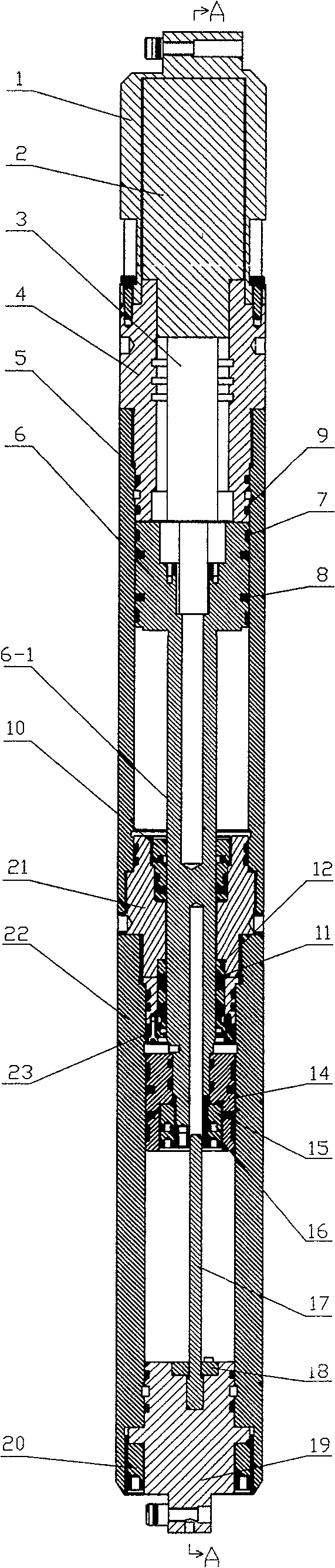
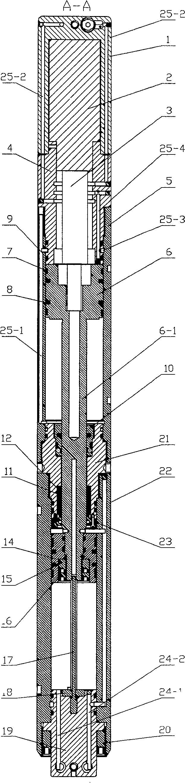
[0011] refer to figure 1 and figure 2 , the high-pressure mixed fluid pump of this embodiment consists of a front adapter 1, a stepping motor 2, an internal control body 3, a control joint 4, an oil cylinder 5, an oil cylinder piston 6, a wear ring 7, a gray ring 8, and a sealing ring 9 , sealing ring 10, dustproof ring 11, guide ring 12, sliding piston 14, first locking ring 15, second locking ring 16, guide rod 17, fixed disk 18, adapter 19, locking ring 20, connector 21, mud cylinder 22, fixed ring 23 form. The oil cylinder 5 and the mud cylinder 22 are threadedly connected to the upper and lower ends of the connector 21, and sealing rings are respectively arranged between the connector 21, the oil cylinder 5 and the mud cylinder 22. The upper end of the oil cylinder 5 is connected with the control joint 4 , the upper end of the control j...


PUM


Abstract

The high-pressure mixed fluid pump relates to a fluid transfer equipment, in the concrete, it relates to a fluid pump which can be used in oil field. Said fluid pump includes the following components: connecting head, oil cylinder, mud cylinder, oil cylinder piston, slide piston, step motor and interior control body. Said invention also provides the action of the above-mentioned every component, and provides the concrete connection mode of all the above-mentioned components.

Description

technical field [0001] The invention relates to a fluid conveying device, in particular to a fluid pump used in an oil field. Background technique [0002] The fluid pumps currently used in oil fields have the following disadvantages: first, the displacement is not easy to control; second, the thrust is small; third, the sealing performance is poor. Contents of the invention [0003] In order to solve the problems in the prior art, the present invention provides a high-pressure mixed fluid pump, which solves the problems in the prior art that the displacement is not easy to control, the thrust is small and the sealing performance is poor. [0004] The high-pressure mixed fluid pump of the present invention includes a connecting head 21, an oil cylinder 5 connected to the upper and lower ends of the connecting head 21 and a mud cylinder 22, an oil cylinder piston 6 arranged inside the oil cylinder 5 and slidingly matched with the oil cylinder 5, arranged inside the mud cyli...

Claims


Application Information

Patent Timeline
Patent Type & Authority Patents(China)
IPC IPC(8): F04B9/10F04B15/02
Inventor 冯永仁庞希顺姜琳杨世祥
Owner CHINA NAT OFFSHORE OIL CORP
Why Eureka
Try Eureka