
Reliability detection device for metal welding part capable of collecting blanking material and its application method

一种金属焊接、检测装置的技术,应用在测量装置、使用施加重复力/脉动力测试材料强度、分析材料等方向,能够解决摩擦力大、缺乏收集断裂金属板装置、无法准确测量金属焊缝冲击力以及冲击力矩的大小等问题,达到移动效率增加、位置准确可控、便于可靠性的效果

Inactive Publication Date: 2018-09-25
SHENZHEN MORGEN PRECISION IND CO LTD
View PDF18 Cites 0 Cited by
  • Summary
  • Abstract
  • Description
  • Claims
  • Application Information

AI Technical Summary

Problems solved by technology

[0004] The above-mentioned patent uses the feeding device to feed the material, then fixes it through the fixing device, and then impacts it by the air pressure rod, but it still has the following problems: 1. The feeding device of the above-mentioned device realizes the position movement of the metal plate to be tested through the telescopic rod and the spring, However, the friction between the metal plate to be tested and the workbench is large, and it is easy to appear that the force of the spring cannot drive the metal plate to be tested; 2. The feeding device of the above-mentioned device realizes position adjustment through the cooperation of the fixing piece and the card slot. The position adjustment of the metal plate is not linear enough, and there can only be several intermittent detection stations, which are prone to misalignment between the weld seam and the edge of the workbench; 3. The above-mentioned device cannot accurately measure the impact force and impact moment on the metal weld seam 4. The metal plate to be tested is easy to collapse and hurt people instantly when it is impacted and broken. The device lacks a device for collecting the broken metal plate, and there is no device for unloading the tested metal plate.

Method used


Image

  • Reliability detection device for metal welding part capable of collecting blanking material and its application method
  • Reliability detection device for metal welding part capable of collecting blanking material and its application method
  • Reliability detection device for metal welding part capable of collecting blanking material and its application method

Examples


Embodiment Construction

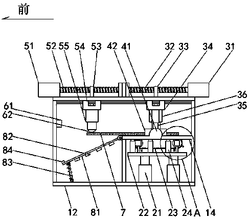
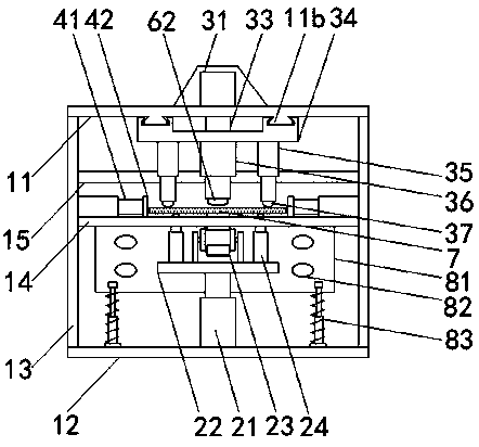
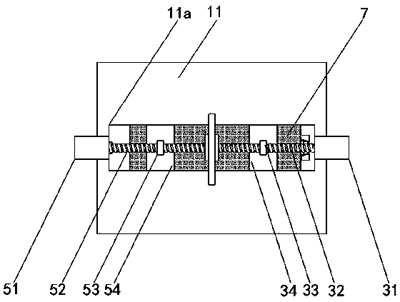
[0051] The present invention is described in further detail now in conjunction with accompanying drawing. These drawings are all simplified schematic diagrams, which only illustrate the basic structure of the present invention in a schematic manner, so they only show the configurations related to the present invention.

[0052] It should be noted that the "front and back" directions mentioned in the manual are the same as those figure 1 The front and rear directions shown in are the same.

[0053] The metal welding part reliability detection device capable of collecting blanking is characterized in that:

[0054] It includes upper and lower base plates (11, 12) arranged in parallel, and the upper and lower base plates (11, 12) are supported and connected by pillars 13, and a workbench 14 is also provided above the rear half of the lower base plate 12, so that The middle part of the upper bottom plate 11 is provided with a moving through hole 11a along the front-rear directio...


PUM


Abstract

The invention relates to a metal welding part reliability detection device capable of collecting and blanking, comprising upper and lower bottom plates, pillars, worktables, and cross bars arranged in parallel; a lifting cylinder and a lifting platform are arranged on the lower bottom plate corresponding to the workbench , synchronous belt conveying device, rolling ball bracket; the rear end of the moving through hole is provided with a first drive motor, a first screw rod, a first screw joint, a first slider, a pre-compression cylinder, a compression cylinder, a second rolling ball; the workbench is also provided with a side cylinder and a limit plate; A laser rangefinder is provided behind the middle part of the cross bar, and a pressure sensor is provided at the lower end of the impact cylinder; a discharge plate, an electromagnet, and a shock absorbing device are hinged at the front end of the workbench; metal welding that can collect blanking The method of using the position reliability detection device includes the steps of feeding, position adjustment, feeding, pressing, impacting, and returning.

Description

technical field [0001] The invention relates to the technical field of metal weld detection, in particular to a metal welding part reliability detection device capable of collecting blanks and a use method thereof. Background technique [0002] The structural strength of metal welds is an important indicator of metal welding quality. Therefore, it is necessary to detect metal welding parts. Traditional welding part detection requires fixing and impacting metal welding samples. During the detection process, manual loading and unloading are required. pieces, labor-intensive and time-consuming. [0003] The application date is 2015.01.06, and the patent application number 201520006550.4 discloses a reliability detection device for welding parts of metal parts, including a workbench, a feeding device, a fixing device and an air pressure rod. There is a hole parallel to the working surface inside the box. The spring is set in the hole and one end is fixed on the top of the hole....

Claims


Application Information

Patent Timeline
Patent Type & Authority Patents(China)
IPC IPC(8): G01N3/307G01N3/36
CPCG01N3/307G01N3/36G01N2203/0044G01N2203/0062
Inventor 荣光其他发明人请求不公开姓名
Owner SHENZHEN MORGEN PRECISION IND CO LTD
Learn More