
Gas compressor

A gas compressor and compressor technology, applied in the field of gas compressors, can solve problems such as poor effect, and achieve the effects of preventing chattering, reliable contact, and improving blade pressure output.

Inactive Publication Date: 2008-09-17
SEIKO INSTR INC
View PDF4 Cites 0 Cited by
  • Summary
  • Abstract
  • Description
  • Claims
  • Application Information

AI Technical Summary

Problems solved by technology

However, increasing the pressure while supplying low pressure will make the effect of reducing the power load mentioned above worse

Method used


Image

  • Gas compressor
  • Gas compressor
  • Gas compressor

Examples


Embodiment Construction

[0042] first embodiment

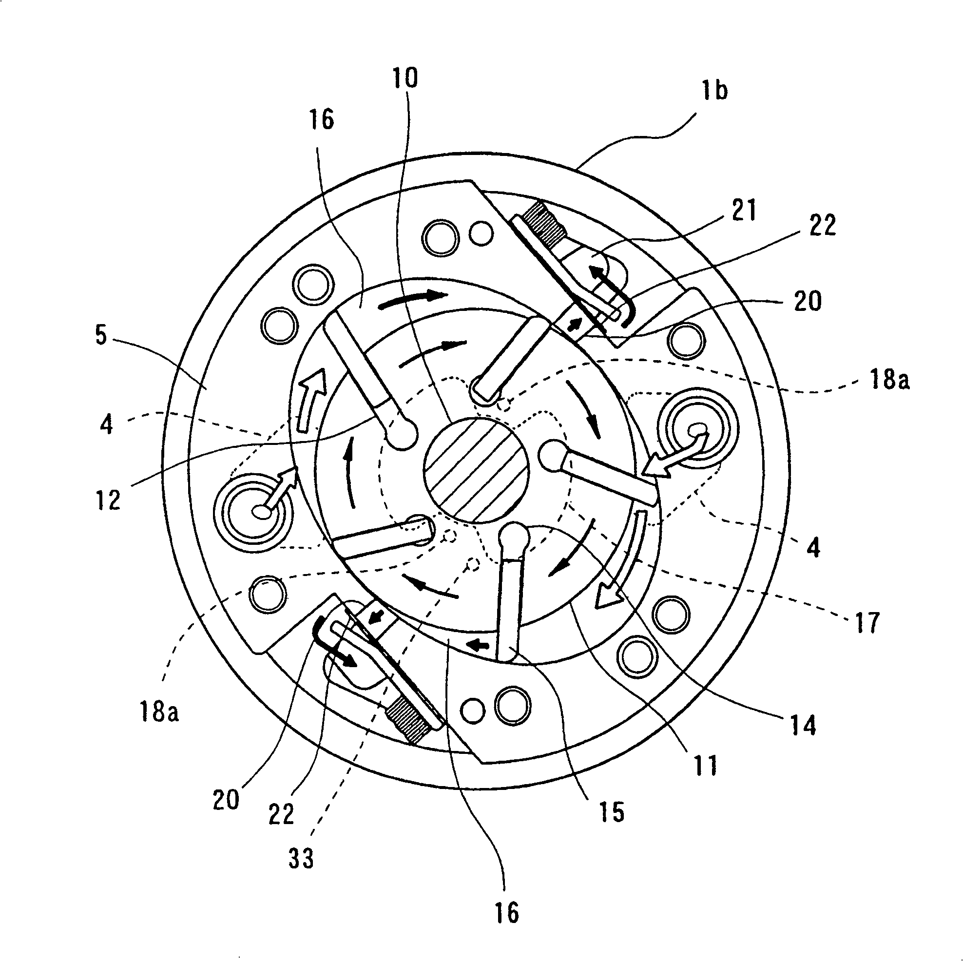
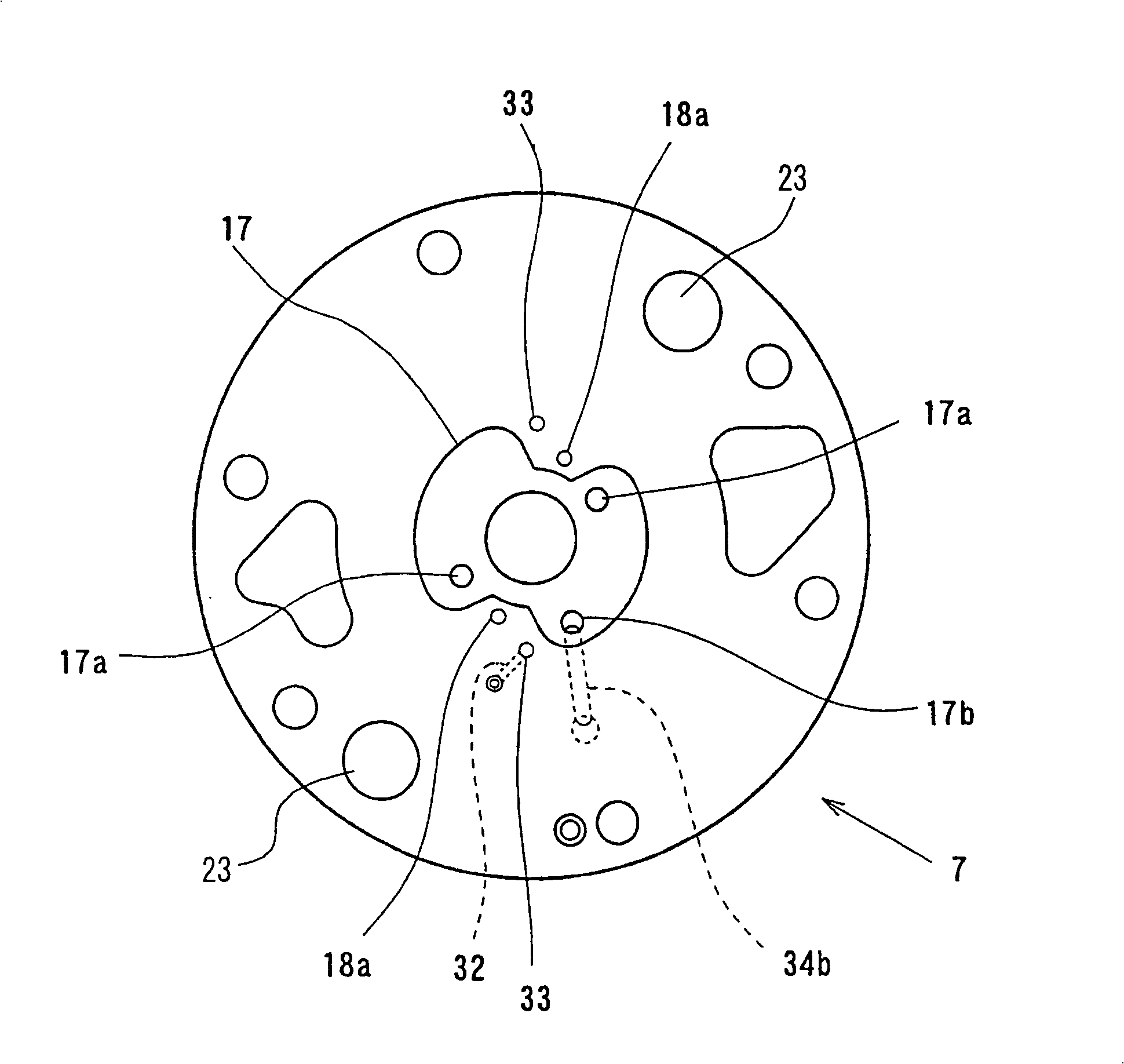
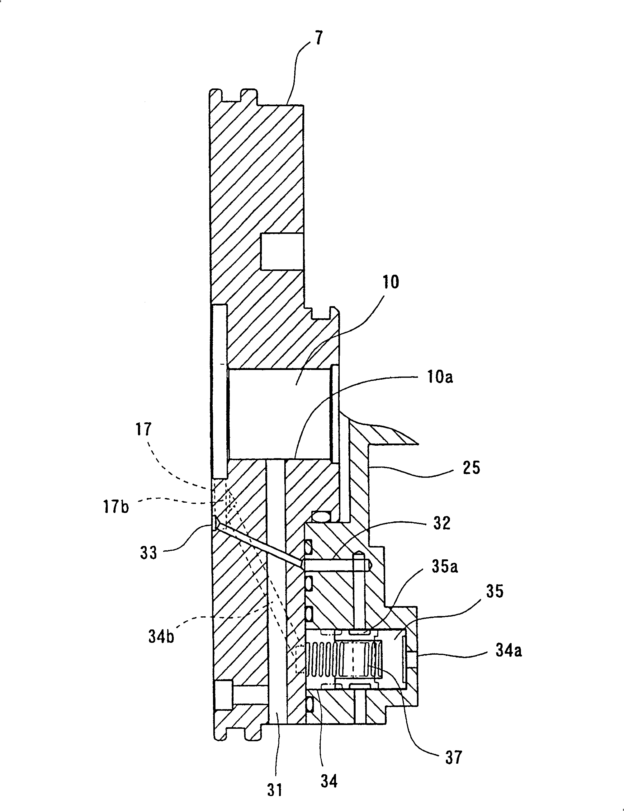
[0043] The following will refer to figure 1 6 to introduce the first embodiment of the present invention. The same components as those in the prior art are denoted by the same reference numerals, and the general structure of the gas compressor will be described with reference to FIG. 10 .

[0044] Like the conventional structure, the gas compressor of the present invention is equipped with a cylinder 5 having an elliptical inner surface, and front and rear side cylinders 6 and 7 arranged at axial ends of the cylinder 5 . The front casing 1 a is mounted on the front side of the front cylinder block 6 , and the rear casing 1 b extends from the rear side of the rear cylinder block 7 to the front cylinder block 6 . The suction port 2 is provided in the front case 1a, and the suction chamber 3 is provided in the front case 1a to communicate with the suction port 2.

[0045] Such as figure 1 As shown, the rotating body 11 is installed in the cylinder 5 ...


PUM


Abstract

To reduce an excessively high vane back pressure to an appropriate pressure to thereby relieve operational load, and to improve the vane projectability at the start and during low speed operation to thereby prevent chattering; There are provided back pressure spaces including the bottom portion of vane grooves and attaining a middle pressure between suction pressure and discharge pressure during normal operation of the compressor main body, a first high pressure oil passage establishing communication between an oil sump and the vane groove bottom portions when the vanes are in their discharge stroke positions, second high pressure oil passages establishing communication between the oil sump and the back pressure spaces, and an opening / closing valve for opening and closing the second high pressure oil passages.

Description

technical field [0001] The present invention relates to a gas compressor suitable for automobile air conditioners or similar devices, which can be used for sucking, compressing and discharging refrigerant gas. Background technique [0002] 10 and 11 show an example of a gas compressor used in a car air conditioner or the like. This compressor is equipped with a cylinder 5 having an elliptical inner surface, and a front side cylinder 6 and a rear side cylinder 7 arranged at axial ends of the cylinder 5 . Inside the cylinder 5 , a rotary body 11 is arranged to be rotatable about a rotary body axis 10 . A plurality of blade grooves 12 extend from the outer peripheral surface of the rotating body 11 to the inner edge, and the blades 15 are respectively accommodated in the blade grooves 12 so as to be able to extend and retract. At the bottom (inner edge side) of each vane groove 12 is provided a back pressure chamber 14 to which pressurized fluid can be supplied. The pressure...

Claims


Application Information

Patent Timeline
Patent Type & Authority Patents(China)
IPC IPC(8): F04C18/344F04C29/02F04C29/12F01C21/08
CPCF01C21/0872
Inventor 高桥彻桑原冲和森田圭一
Owner SEIKO INSTR INC
Learn More