Stator iron core for rotary electric machine

A technology of stator iron core and rotary motor, which is applied in the direction of magnetic circuit shape/style/structure, magnetic circuit static parts, etc., and can solve problems such as poor assembly.

Inactive Publication Date: 2008-11-12
TOYO DENSO
View PDF4 Cites 0 Cited by
  • Summary
  • Abstract
  • Description
  • Claims
  • Application Information

AI Technical Summary

Problems solved by technology

[0004] The problem to be solved is that in the existing stator core, each core element is engaged with each other through claws or concave-convex parts, so the core elements have to be inserted and assembled from the side one by one, and the assembly is not good.

Method used


Image

  • Stator iron core for rotary electric machine
  • Stator iron core for rotary electric machine
  • Stator iron core for rotary electric machine

Examples


Embodiment Construction

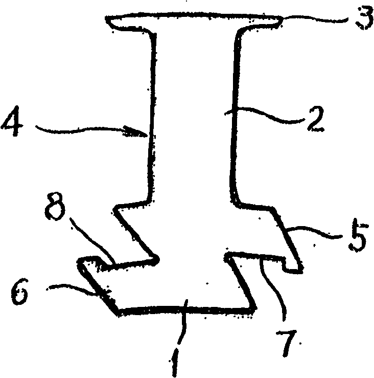
[0018] In the stator core of the rotary electric machine of the present invention, such as figure 1 As shown, the core element 4 is divided into magnetic pole units composed of a yoke portion 1 , a magnetic pole portion 2 , and a claw portion 3 .

[0019] In the core element 4, the lower protruding arm part 5 is provided in the upper stage of one side of the yoke part 1, and the upper protruding arm part 6 is provided in the lower stage of the other side.

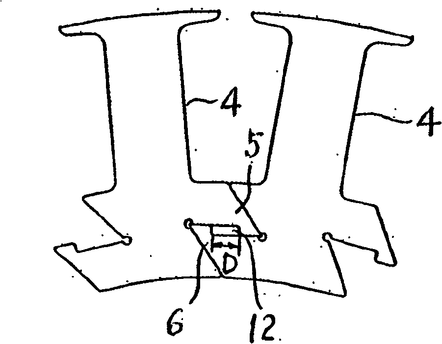
[0020] In addition, a notch 7 is formed on the lower protruding arm portion 5, and a notch 8 is formed on the upper protruding arm portion 6, as figure 2 As shown, the facing downward protruding arm portions 5 and upward protruding arm portions 6 on adjacent core elements 4 are movably engaged with each other within a predetermined range D along the adjacent direction (circumferential direction).

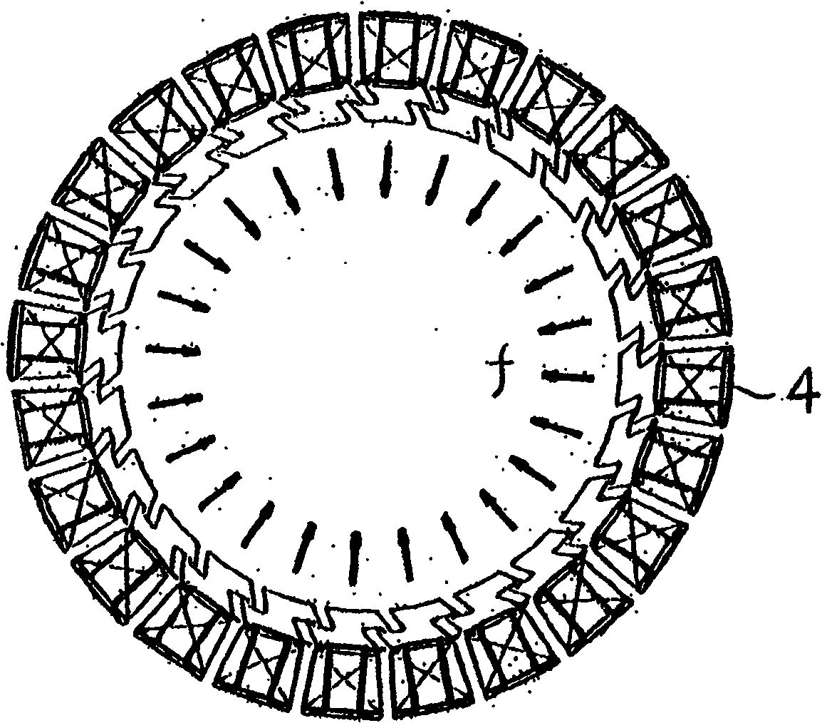
[0021] So, if image 3 and Figure 4 As shown, in the state where the fixed number of core elements 4 are arranged in a ci...


PUM


Abstract

This relation relates to a stator iron core of a rotary motor, in which, the iron core elements are combined at the magnetic yoke to be assembled to a round body, said elements are divided into magnetic pole units composed of a magnetic yoke part of outer rotor stator core, a pole part and a claw part, this time, a lower projection arm is set at one side of the yoke and an upper projection arm is set at the other side, the opposite upper and lower projection arms on the adjacent core elements can be jointed movably in the specified sphere along the peripheral direction to a round body and a bolt is plug into the hole formed by the joint parts of the arms to be fixed to one unit.

Description

technical field [0001] The present invention relates to an outer rotor type stator core of a rotary electric machine, in particular to a stator core of a rotary electric machine constituted by a unit structure. Background technique [0002] In the prior art, such as Figure 8 As shown, the core element 4 divided into the magnetic pole unit composed of the yoke portion 1, the magnetic pole portion 2 and the claw portion 3 of the outer rotor type stator core is divided into one side and the other side of the yoke portion 1 of each core element 4. The downward claws 24 and the upward claws 25 are respectively provided, and each adjacent core element is engaged with each other through the engagement of the downward claws 24 and the upward claws 25, and a plurality of core elements are assembled into a circular body. (Refer to Japanese Unexamined Patent Publication No. 2000-50583). [0003] In addition, in the prior art, there is an inner rotor type stator core, and there are al...

Claims


Application Information

Patent Timeline
Patent Type & Authority Patents(China)
IPC IPC(8): H02K1/12
Inventor 八野井聪福岛健夫山崎正
Owner TOYO DENSO
Why Eureka
Try Eureka