Piezoelectric valve and method for manufacturing said piezoelectric valve

A manufacturing method and piezoelectric technology, applied in piezoelectric effect/electrostrictive or magnetostrictive motors, piezoelectric devices/electrostrictive devices, piezoelectric/electrostrictive/magnetostrictive devices, etc., It can solve the problems of inaccurate movement and small stroke, and achieve the effect of excellent water resistance and high compressibility

Pending Publication Date: 2021-11-30
SATAKE CORP +1
View PDF3 Cites 0 Cited by
  • Summary
  • Abstract
  • Description
  • Claims
  • Application Information

AI Technical Summary

Problems solved by technology

In this case, there is a possibility that the operation of the multi-layer piezoelectric element may be hindered, the stroke may be reduced, or accurate operation may not be possible.

Method used


Image

  • Piezoelectric valve and method for manufacturing said piezoelectric valve
  • Piezoelectric valve and method for manufacturing said piezoelectric valve
  • Piezoelectric valve and method for manufacturing said piezoelectric valve

Examples


Embodiment Construction

[0048] Embodiments of the present disclosure will be described based on the drawings.

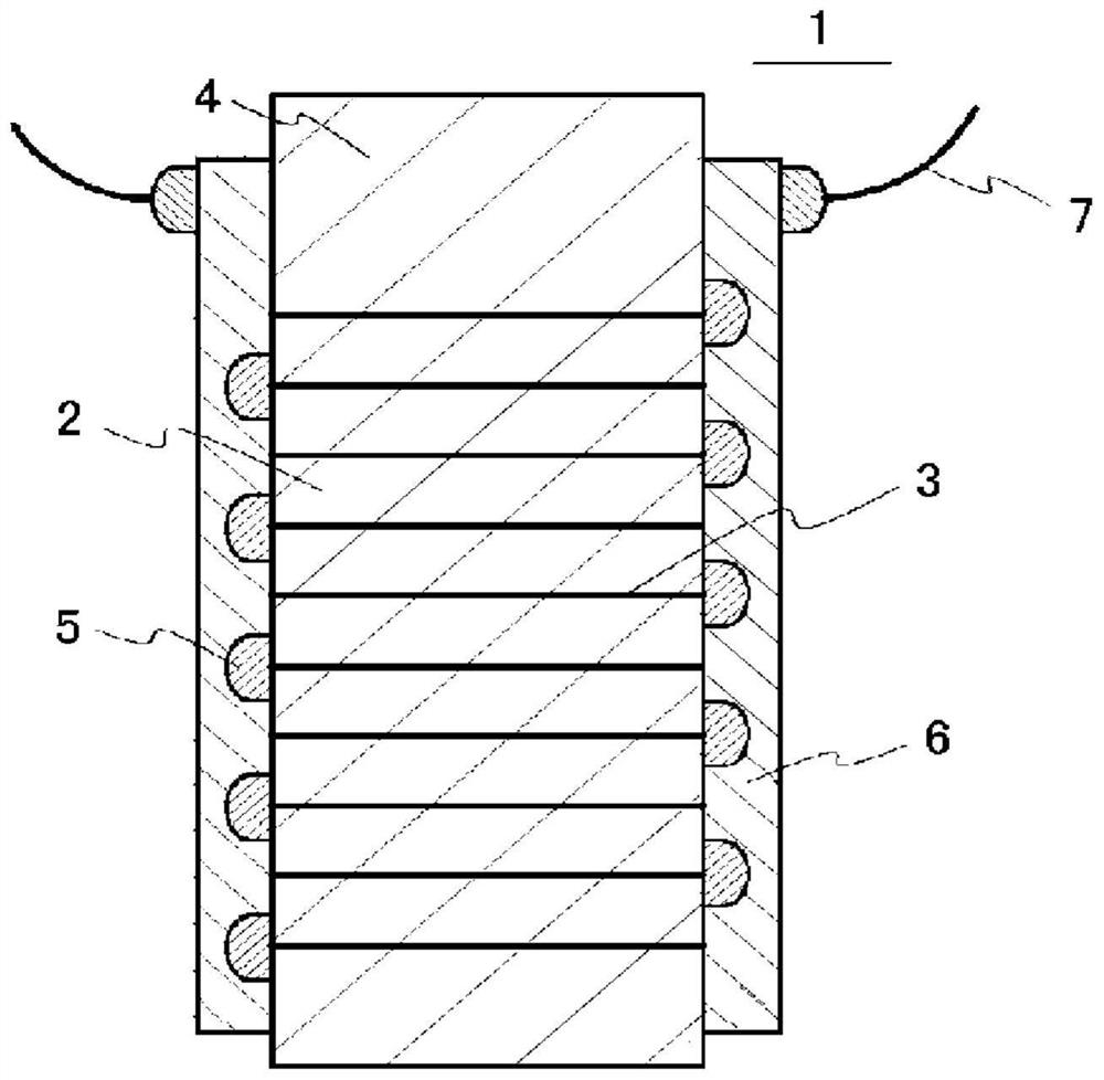
[0049] figure 1 It is a representative example of a multilayer piezoelectric element (hereinafter, referred to as a "piezoelectric element"), and shows a cross-sectional view.

[0050] figure 1 The illustrated piezoelectric element 1 has a laminated body 4 in which piezoelectric ceramic layers 2 and internal electrode layers 3 are alternately laminated. The internal electrode layer 3 is exposed on the side surface of the laminated body 4 . The exposed side surfaces of each of the internal electrode layers 3 are covered with insulating layers 5 every other layer. Furthermore, the laminated body 4 has the external electrode 6 which covers the insulating layer 5 and is electrically connected to the internal electrode layer 3 which is not covered with the insulating layer 5 .

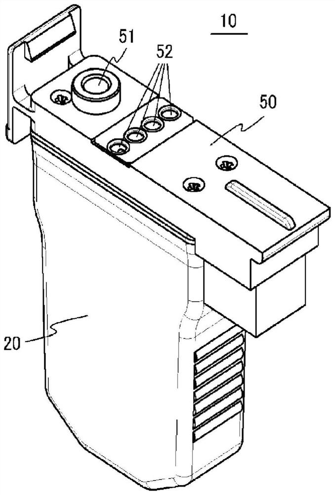
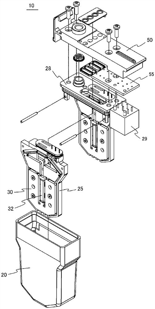
[0051] figure 2 It is an example of a piezoelectric valve, and shows a perspective view. image 3 express fig...


PUM


Abstract

Provided is a piezoelectric valve with which the following can be prevented: a broken piece of a layered piezoelectric element is ejected together with a compressed gas during use; the lifespan is shortened due to the infiltration of moisture into the layered piezoelectric element when used in a high-humidity environment; and stroke size is decreased or accurate operation is hindered due to obstruction of the movement of the layered piezoelectric element. Disclosed is the piezoelectric valve in which displacement of a layered piezoelectric element is utilized to open / close a valve, the piezoelectric valve comprising: a valve body having a gas pressure chamber that receives a compressed gas supplied from the outside; and an actuator that is disposed in the valve body, and that has a valve element, a layered piezoelectric element that generates as displacement a driving force necessary for operating the valve element, and a displacement enlarging mechanism that enlarges the displacement of the layered piezoelectric element and causes the enlarged displacement to act on the valve element, wherein the piezoelectric valve is characterized in that a surface of the layered piezoelectric element is coated with silicone in a state of being integrated with the actuator.

Description

technical field [0001] The present disclosure relates to a piezoelectric valve that opens and closes the valve by utilizing displacement of a laminated piezoelectric element, and a method of manufacturing the piezoelectric valve. Background technique [0002] Conventionally, there has been known a piezoelectric valve that opens and closes the valve and discharges compressed gas by utilizing the displacement of a multi-layer piezoelectric element (see Patent Document 1). [0003] The piezoelectric valve described in Patent Document 1 utilizes the characteristics of a multilayer piezoelectric element with excellent high-speed response performance, and includes a displacement amplification mechanism that amplifies a small displacement of the multilayer piezoelectric element based on the principle of leverage. [0004] In the piezoelectric valve, when a voltage is applied to the laminated piezoelectric element, the displacement of the laminated piezoelectric element in the direc...

Claims


Application Information

Patent Timeline
Patent Type & Authority Applications(China)
IPC IPC(8): H02N2/04F16K31/02F16K31/44H01L41/053H01L41/09
CPCH02N2/043F16K31/007H10N30/883H10N30/50F16K31/004F16K31/02F16K31/44H02N2/04H10N30/88H10N30/20
Inventor 伊藤隆文松下忠史樋口俊郎徐世杰水野义宣
Owner SATAKE CORP
Why Eureka
Try Eureka