Turbine fan

A turbo fan and fan blade technology, which is applied in the field of turbo fans, can solve the problems of high manufacturing cost and increased manufacturing cost, and achieve the effects of reducing manufacturing cost, improving yield and ensuring quality.

Inactive Publication Date: 2016-05-04
NISSHINBO MECHATRONICS
View PDF7 Cites 0 Cited by
  • Summary
  • Abstract
  • Description
  • Claims
  • Application Information

AI Technical Summary

Problems solved by technology

Therefore, the turbofan 9 of Patent Document 3 also has the problem of high manufacturing cost.
[0010] Furthermore, the vane 9 is constituted by joining the two members 91 and 92, and requires equipment, time and energy for joining the vane member 91 and the vane member 92, and there is also a problem of further increase in manufacturing cost.

Method used


Image

  • Turbine fan
  • Turbine fan
  • Turbine fan

Examples


Embodiment

[0108] Examples and comparative examples

[0109] Hereinafter, examples and comparative examples are given to describe the turbo fan of the present invention and the turbo fan of a comparative example (Patent Document 3).

[0110] [Example]

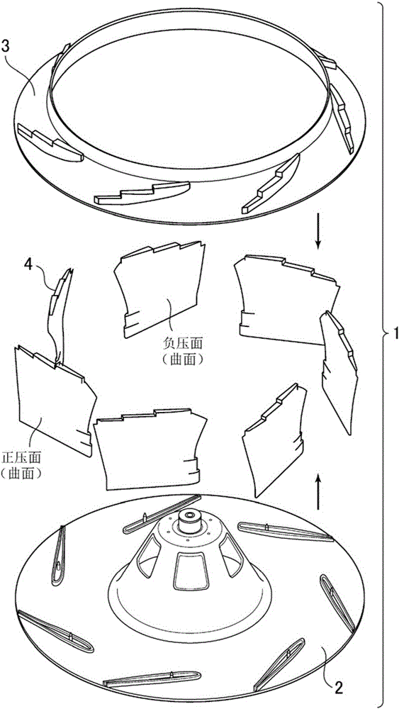
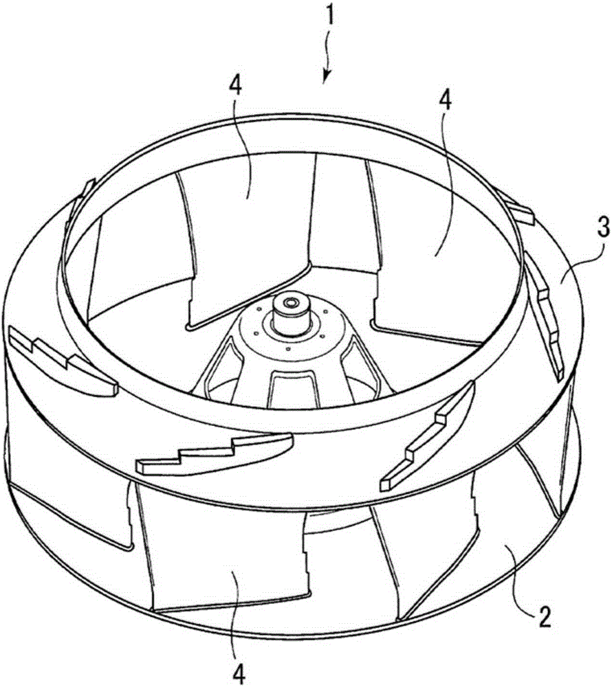
[0111] In this embodiment, acrylonitrile-butadiene-styrene (acrylonitrile-butadiene-styrene, ABS) resin is used for injection molding, respectively, as figure 1 The main board 2, the wind deflector 3, and the fan blade member 4 (component 41 and component 42) are the components of the turbofan. In addition, in the blade member 4, the member 41 and the member 42 are inserted into each other and integrated to produce a turbofan.

[0112] These components are like It is integrally formed as described in "Assembly and Joining of Turbo Fan." Regarding the processing conditions of ultrasonic welding, the pressing force was set to 0.1 to 0.2 MPa, the power of the welding machine was set to 2000 W, and the pressing time was set to 1.0 second. The tu...


PUM


Abstract

The invention is to provide a turbine fan. A main board, an air guide plate and a plurality of fan blade components are made from thermoplastic resin; the main board is provided with a projected hub fixed on a rotating shaft of a motor; the air guide plate forms an absorbing air guide wall; the main board is provided with a plurality of embedded part embedded with the plurality of fan blade components; the air guide plate is provided with a plurality of embedded part embedded with the plurality of fan blade components, so the plurality of fan blades can be embedded to the main board and the plurality of embedded parts in a way of being parallel to the rotating shaft and are welded together via ultrasonic wave. The turbine fan has excellent productbility and low price compared with turbine fans in the prior art.

Description

Technical field [0001] The present invention relates to a turbofan that is mounted on an air conditioner and is molded from a thermoplastic resin, and relates to a turbofan that has improved weldability and productivity. Background technique [0002] A conventional turbofan includes a fan main body formed by integrally molding a main plate and a plurality of wings having a bag-like hollow structure with openings on the back side using a thermoplastic resin, and a wind deflector. In addition, each wing of the fan body is formed with a female fitting portion communicating from the tip of the wing to the hollow portion of the wing, and a male fitting extending from the wind deflector in the height direction of the fan is formed at the position corresponding to each wing of the wind deflector. United. [0003] Moreover, after the male fitting part of the air deflector is inserted into the female fitting part of the fan body, the surface of the air deflector, the wing tip welding part ...

Claims


Application Information

Patent Timeline
Patent Type & Authority Applications(China)
IPC IPC(8): F04D29/30F04D29/44
Inventor 渡辺仁岩井晴义加藤贵久
Owner NISSHINBO MECHATRONICS
Why Eureka
Try Eureka