Energy indicator used in screw bolt refrigerant compressor

A refrigeration compressor and indicator technology, which is applied in the direction of machines/engines, mechanical equipment, liquid fuel engines, etc., can solve problems such as inconvenient operation, limited viewing angle, personal safety threats, etc., and achieve the effect of easy implementation and simple structure

Inactive Publication Date: 2008-11-26
YANTAI MOON
View PDF5 Cites 0 Cited by
  • Summary
  • Abstract
  • Description
  • Claims
  • Application Information

AI Technical Summary

Problems solved by technology

However, most of the energy indicator panels of conventional screw refrigeration compressors are on the side of the suction end of the screw compressor, and users cannot directly observe them in front of the console, but need to stand on the side of the suction end of the compressor to observe them. It brings great inconvenience to the operation
There are also energy indicators of some screw refrigeration compressors (such as single-unit two-stage screw refrigeration compressors) that need to be set under the coupling between the compressor and the motor, and can only be observed when operating close to the bottom of the coupling, which poses a threat to personal safety. Possesses a great threat, while the observation angle is more restricted

Method used


Image

  • Energy indicator used in screw bolt refrigerant compressor
  • Energy indicator used in screw bolt refrigerant compressor

Examples


Embodiment Construction

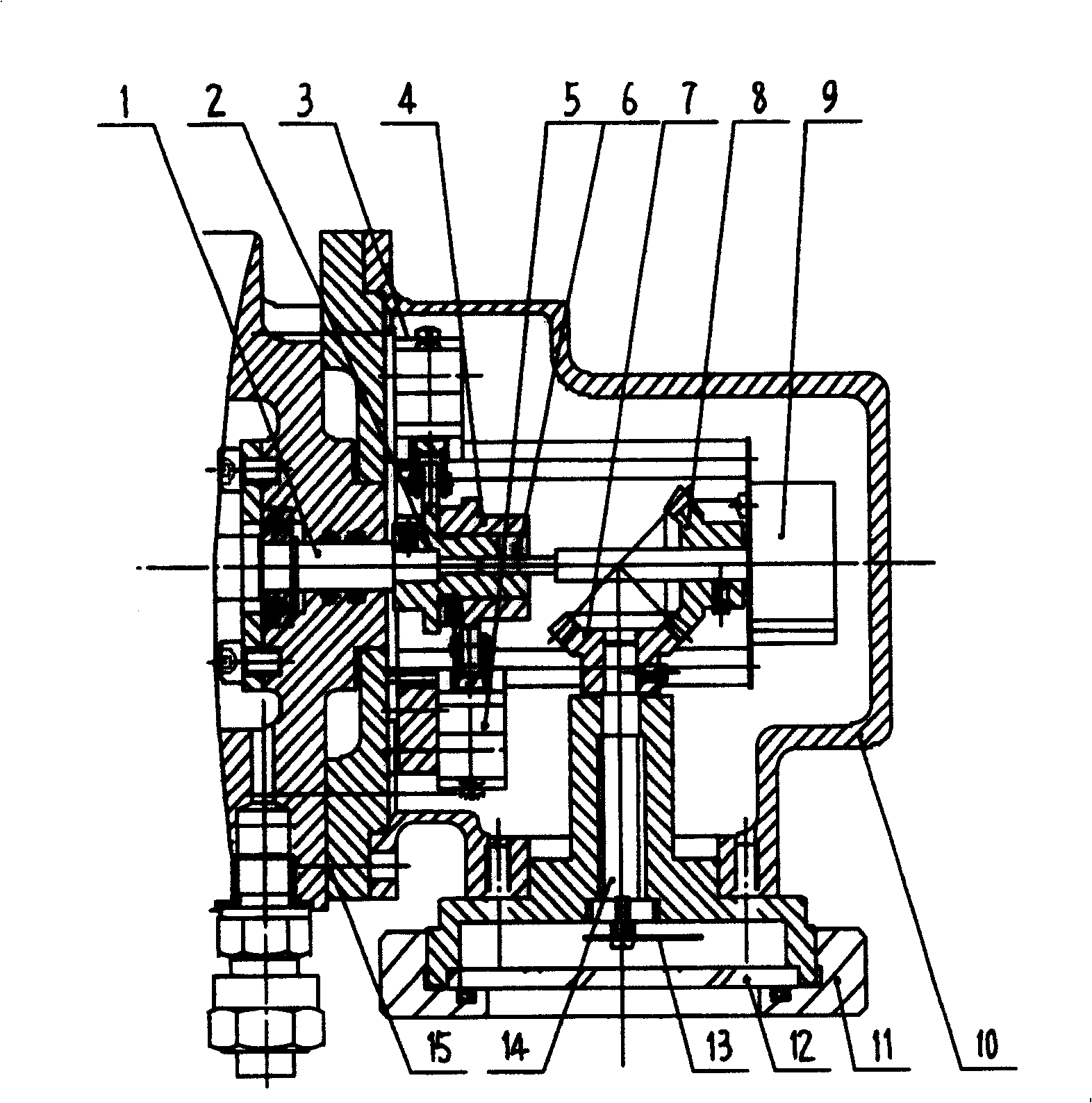
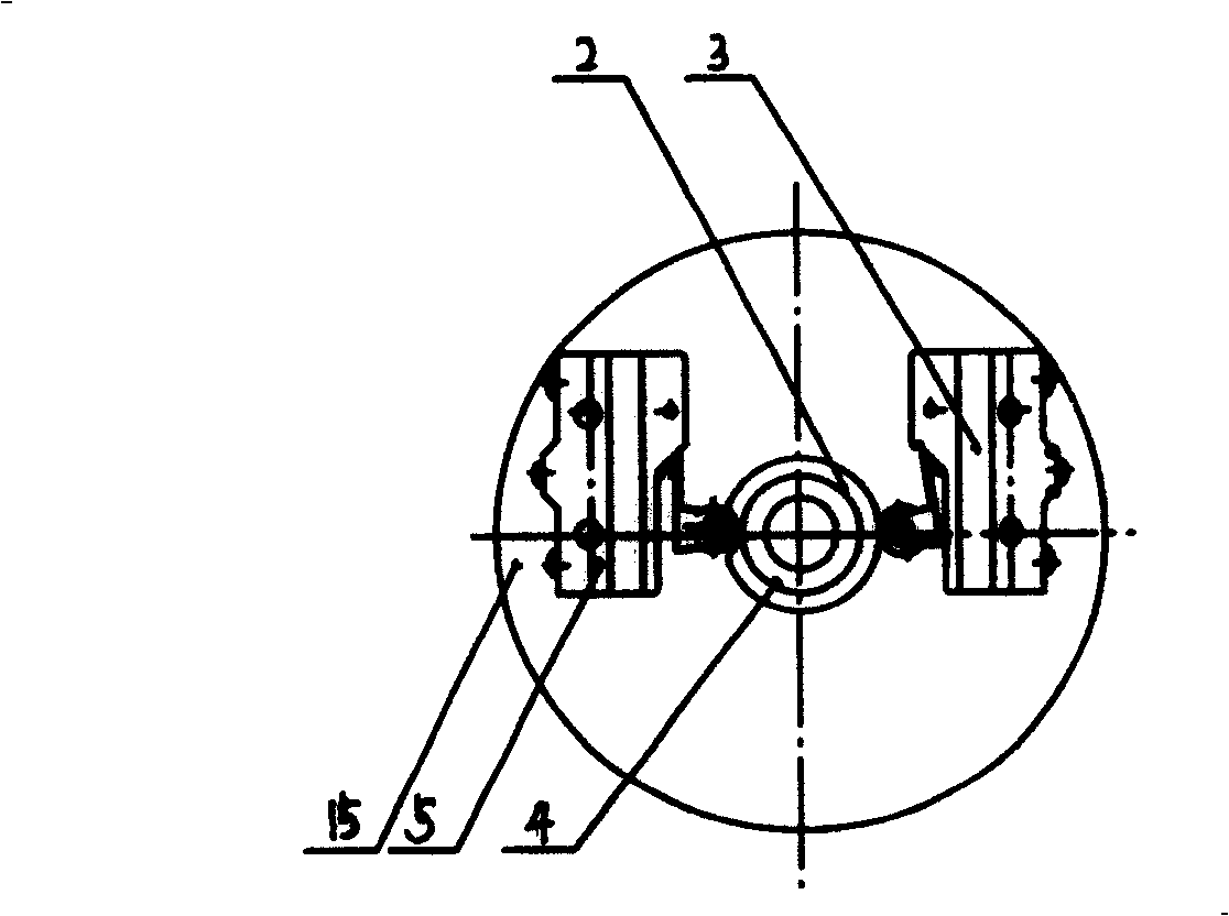
[0014] The present invention will be described in detail below in conjunction with the accompanying drawings.

[0015] like figure 1 As shown, the screw rod 1, the micro switch cam A 2 and the micro switch cam B 4 are fixed together by set screws. like figure 2 As shown, the two microswitch cams are respectively provided with a groove in the form of a semicircular notch, and the positions of their rollers roll along the outer circles of microswitch cam A and microswitch cam B respectively. When they were respectively to the roller wheels on the microswitch first 3 and microswitch second 5, they had just reached the maximum and minimum corner positions. The rod of the potentiometer 9 is connected with the groove on the microswitch cam A 2 through the positioning pin 6 thereon. The potentiometer 9 is connected with the first bevel gear 8 by screws. The second bevel gear 7 and the pointer 13 are fixed on the second bevel gear fixed shaft 14 . The indicator plate 12 is fixed...


PUM


Abstract

The invention relates to an energy instructor of screw refrigerating compressor, wherein the outer end of a screw rod 1 is fixed with a first micro-motion switch cam 2 fixed with a second micro-motion switch cam 4, the rod of a potentiometer 9 is fixed with the first micro-motion switch cam, the rod is also fixed with a first taper gear 8, one end of a second taper gear axle 14 is fixed with a second taper gear meshed with the first taper gear 8 while another end is fixed with a point 13, an instructing base 15 is fixed with a first micro-motion switch 3 and a second micro-motion switch 5, whose rollers are respectively connected with the circumferences of the first and second micro-motion switch cams 2, 4. The invention moves the axle of the sliding valve to be vertical and forward, therefore, user can watch the instructing disc flexibly.

Description

technical field [0001] The invention relates to an energy indicator used as a part of a screw refrigeration compressor, which is installed at the suction end or discharge end of the screw refrigeration compressor. Background technique [0002] During the use of the screw refrigeration compressor, it is often necessary to change the position of the energy adjustment slide valve according to the load change, so that the volume flow of the compressor can adapt to the gas consumption of the actual working condition. In order to accurately indicate the moving position of the slide valve, an energy adjustment indicator component is arranged at the suction end or the discharge end of the screw refrigeration compressor. However, most of the energy indicator panels of conventional screw refrigeration compressors are on the side of the suction end of the screw compressor, and users cannot directly observe them in front of the console, but need to stand on the side of the suction end o...

Claims


Application Information

Patent Timeline
Patent Type & Authority Patents(China)
IPC IPC(8): F04C18/16F04C29/00
Inventor 姜韶明杨永才韩博飞王楠张希良缪会军
Owner YANTAI MOON
Why Eureka
Try Eureka