
Milling cutter edge grinding machine

A grinding machine and blade technology, applied in milling cutters, milling machine equipment, metal processing equipment and other directions, can solve the problems of cumbersome, tool breakage, complicated operation process, etc., to increase economic benefits, improve service life, and reduce costs.

Inactive Publication Date: 2008-12-03
徐东杰
View PDF6 Cites 0 Cited by
  • Summary
  • Abstract
  • Description
  • Claims
  • Application Information

AI Technical Summary

Problems solved by technology

[0002] As we all know, after the milling cutter is used for a period of time, the main cutting edge and the bottom edge of the milling cutter will be worn to varying degrees, which will affect the surface finish, processing size and milling speed of the processed parts. If the milling cutter continues to be used, it will easily cause the cutter to break Even damage the size and shape of the processed parts, and even cause personal injury to the operator in severe cases
At present, there are generally two types of repair and sharpening for worn milling cutters: tool grinder sharpening and manual sharpening. The former is not a special equipment for sharpening milling cutters, and requires professional tool grinding operations. The operation process is complicated and cumbersome. Low efficiency; the latter is manually operated on a grinder to sharpen the milling cutter. Technical problems such as the geometric angle and coaxiality of the milling cutter are difficult to control. A slight mistake will cause the milling cutter to be scrapped

Method used


Image

  • Milling cutter edge grinding machine
  • Milling cutter edge grinding machine
  • Milling cutter edge grinding machine

Examples


Embodiment Construction

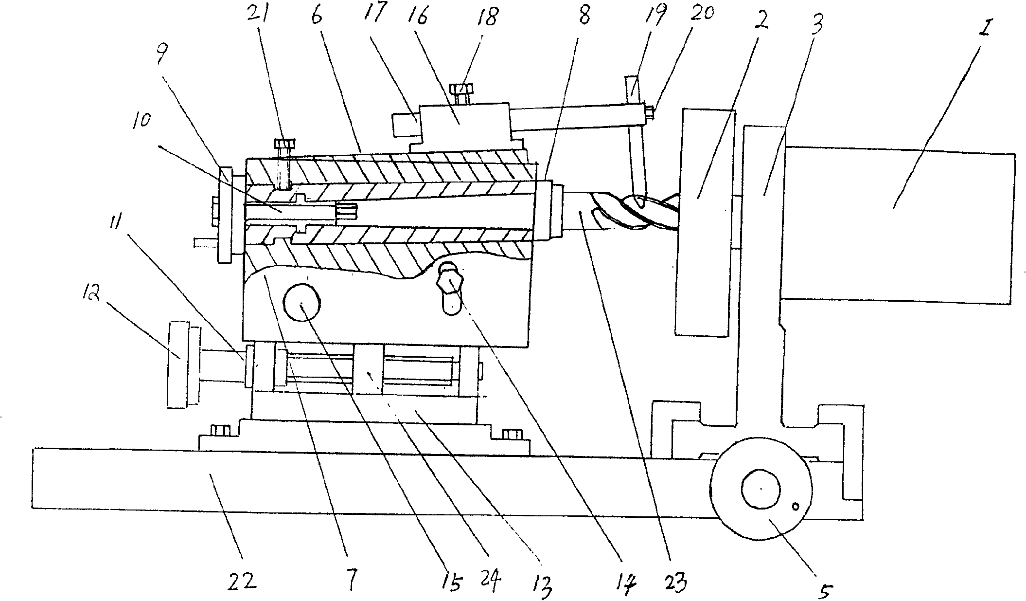
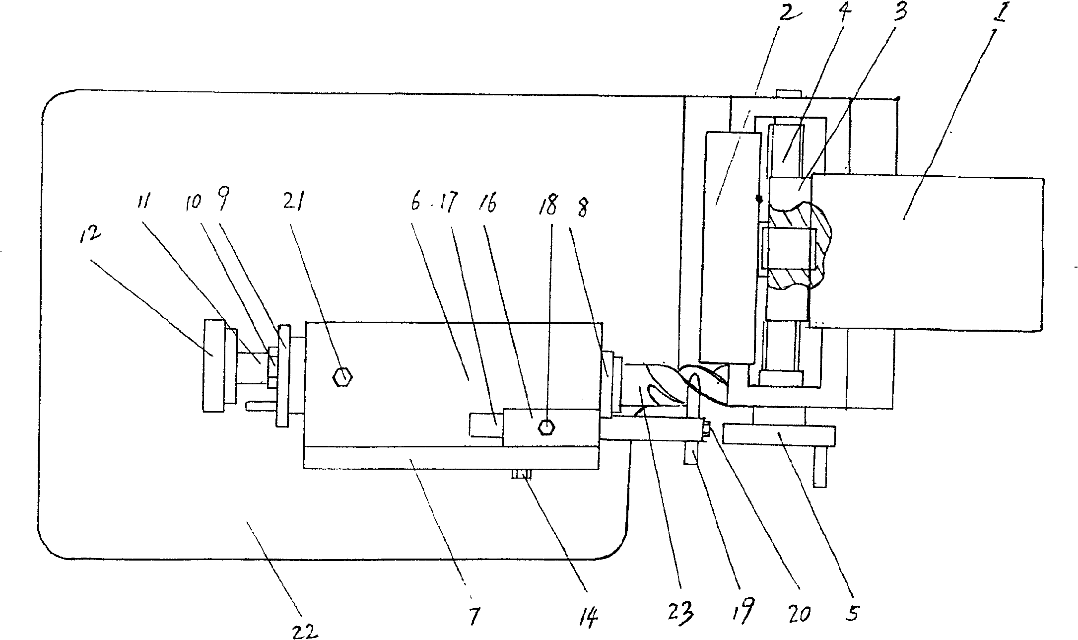
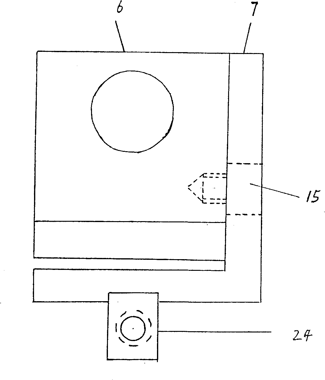
[0009] In order to better understand the present invention, it will be further described in detail below in conjunction with the accompanying drawings and embodiments.

[0010] refer to Figure 1-Figure 3 Visible, milling cutter sharpening of the present invention mainly is by working platform 22, frame plate base 13 and motor support 3 that are fixed on it, motor 1 is housed on the motor support 3, the emery wheel 2 that links to each other with motor, It is composed of the frame plate 7 fixed on the frame plate seat 13, the grinding wheel 2 is fixed on the output end of the output shaft of the motor 1, and there is a longitudinal transmission screw 4 passing through the working platform 22 under the motor support 3, and the longitudinal transmission wire One end of bar 4 is fixed, and the other end is equipped with handle 5, and the bottom of motor support 3 is provided with the first screw nut that cooperates with longitudinal transmission lead screw 4; The plate base 13 i...


PUM


Abstract

The invention relates to a blade milling machine that includes workbench, frame board base, and dynamo support, and the dynamo is installed on the dynamo support and frame board is fixed on frame board base. The feature is that the output of dynamo is fixed a grinding wheel, and portrait drive leading screw is set on the downward of the dynamo support. Master screw matched with leading screw is set on the bottom of the dynamo support. And master screw is also set on the bottom of frame board. Athwart drive lead screw is set on the frame board base, blade tool base connects to the frame board through center axis; sliding taper sleeve is set in the blade tool. One end of taper sleeve is set a milling cutter and the other end is set a handle. On the top of the blade tool base frame, a gird support is set, and the sliding gird is fixed through athwart hole; on end of the sliding athwart is set an orient division guiding bar. The invention has the advantages of reasonable structure, easy to operate, prolonging the useful life of milling cutter, and saving cost.

Description

1. Technical field [0001] The invention relates to a sharpening tool, in particular to a sharpening tool for sharpening a cylindrical milling cutter. 2. Background technology [0002] As we all know, after the milling cutter is used for a period of time, the main cutting edge and the bottom edge of the milling cutter will be worn to varying degrees, which will affect the surface finish, processing size and milling speed of the processed parts. If the milling cutter continues to be used, it will easily cause the cutter to break Even damage the size and shape of the processed parts, and even cause personal injury to the operator in severe cases. At present, there are generally two types of repair and sharpening for worn milling cutters: tool grinder sharpening and manual sharpening. The former is not a special equipment for sharpening milling cutters, and requires professional tool grinding operations. The operation process is complicated and cumbersome. The efficiency is low...

Claims


Application Information

Patent Timeline
Patent Type & Authority Patents(China)
IPC IPC(8): B24B3/02
Inventor 徐东杰
Owner 徐东杰
Learn More