Clock phase detecting device and method

A phase detection and clock technology, applied in the field of clock phase detection devices, can solve the problems of limited clock phase detection accuracy, multiple logic resources, and inability to increase, and achieve the effect of improving the clock phase detection accuracy

Inactive Publication Date: 2008-12-10
GLOBAL INNOVATION AGGREGATORS LLC
View PDF2 Cites 0 Cited by
  • Summary
  • Abstract
  • Description
  • Claims
  • Application Information

AI Technical Summary

Problems solved by technology

[0010] However, the increase of N value must mean the increase of the number of phase detectors, which will consume more logic resources
Moreover, the increase of the N value will also lead to the reduction of the phase interval between the phase detectors, and the current technical capabilities usually cannot increase the N value to more than 10
It can be seen that the method of using N phase detectors for phase detection not only consumes more logic resources, but also has a limited improvement in the accuracy of clock phase detection.

Method used


Image

  • Clock phase detecting device and method
  • Clock phase detecting device and method
  • Clock phase detecting device and method

Examples


Embodiment Construction

[0040] The present invention will be described in detail below in conjunction with the accompanying drawings and specific embodiments.

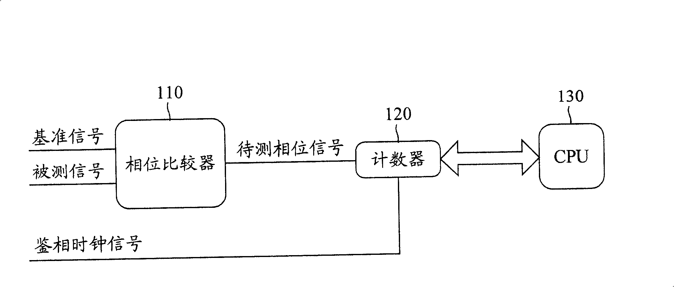
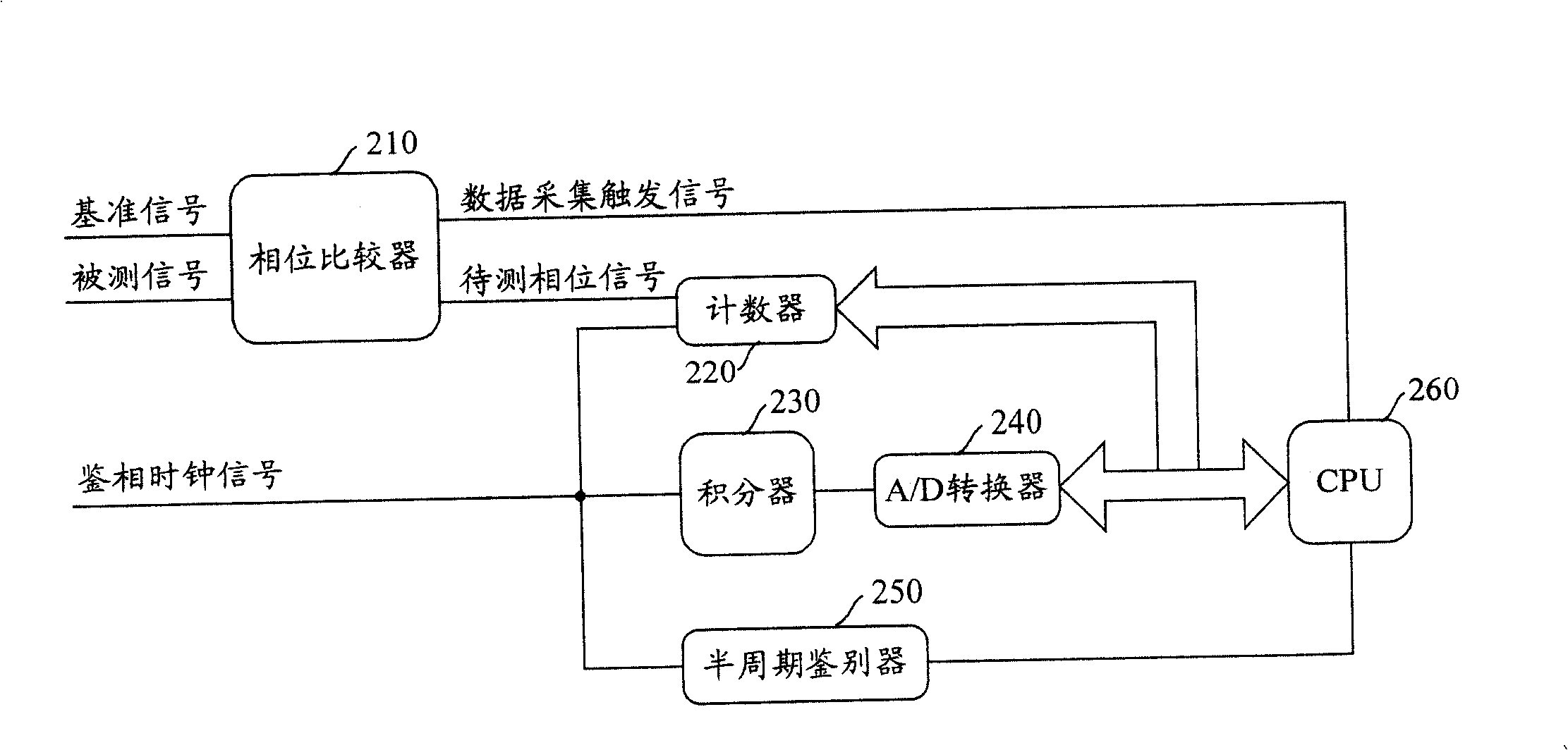
[0041]The clock phase detection device provided by the present invention includes a connected counter and a CPU, and also includes a digital quantity integration result acquisition unit connected to the CPU; wherein, the counter is used to receive a continuous phase detection clock signal and can reflect the reference signal and the measured signal phase difference between phase signals to be measured, and accumulate the phase detection clock signal quantity that can be accommodated in the phase width of the phase signal signal to be measured, and then send the accumulated phase detection clock signal quantity to the CPU; the digital quantity integration result acquisition unit uses To receive the phase discrimination clock signal and perform symmetrical integration and analog-to-digital conversion to obtain the phase discrimination clock sign...


PUM


Abstract

The invention discloses a clock phase discrimination device and method, which are used for measuring the phase difference between a reference signal and a signal to be measured; both need to obtain a phase signal to be measured that can reflect the phase difference between the reference signal and the signal to be measured. The number of phase detection clock signals that can be accumulatively accommodated within the phase width of the phase signal to be measured; and by symmetrically integrating the continuous phase detection clock signal, the integration result of the digital quantity phase detection clock signal within the phase width of the phase signal to be measured is obtained, and then Obtain the phase value of the phase detection clock signal when the integration result of the phase detection clock signal is obtained; then, calculate the phase of the phase detection signal according to the obtained phase value of the phase detection clock signal and the accumulated number of phase detection clock signals width. The device and method of the invention can significantly improve the precision of clock phase discrimination.

Description

technical field [0001] The invention relates to clock technology, in particular to a clock phase detection device and method. Background technique [0002] No matter in the field of communication or in other fields, clock technology has developed very maturely; clock technology includes two key technologies: clock phase detection technology and phase locking technology. [0003] Among them, the clock phase detection technology is used to measure the phase difference of two signals, these two signals are usually the reference signal and the signal under test; the reference signal is a standard clock signal, which has the desired ideal phase when the clock signal is applied , the measured signal is an actual applied clock signal, and its phase is not necessarily the same as that of the reference signal. The purpose of clock phase detection is to accurately measure the phase difference between the reference signal and the measured signal, so as to obtain various clock indicato...

Claims


Application Information

Patent Timeline
Patent Type & Authority Patents(China)
IPC IPC(8): H03L7/08H03L7/18H04L7/00
Inventor 黄鸿贵
Owner GLOBAL INNOVATION AGGREGATORS LLC
Why Eureka
Try Eureka