A Lead-Lag Digital Phase Detector Structure

A digital phase detector and hysteresis type technology, applied in the direction of automatic power control, electrical components, etc., can solve the problem of low phase detection accuracy of the digital phase detector

Active Publication Date: 2019-04-23
SOI MICRO CO LTD
View PDF5 Cites 0 Cited by
  • Summary
  • Abstract
  • Description
  • Claims
  • Application Information

AI Technical Summary

Problems solved by technology

[0006] The technical problem to be solved by the present invention is to provide a high-precision lead-lag digital phase detector structure, which solves the technical problem of low phase detection accuracy of digital phase detectors in the prior art

Method used


Image

  • A Lead-Lag Digital Phase Detector Structure
  • A Lead-Lag Digital Phase Detector Structure
  • A Lead-Lag Digital Phase Detector Structure

Examples


Embodiment Construction

[0041] The present invention will be further described in detail below in conjunction with the accompanying drawings and specific embodiments of the present invention. It should be understood that the present invention is not limited to the specific embodiments described below, and those skilled in the art may make various variations or modifications within the scope of the appended claims.

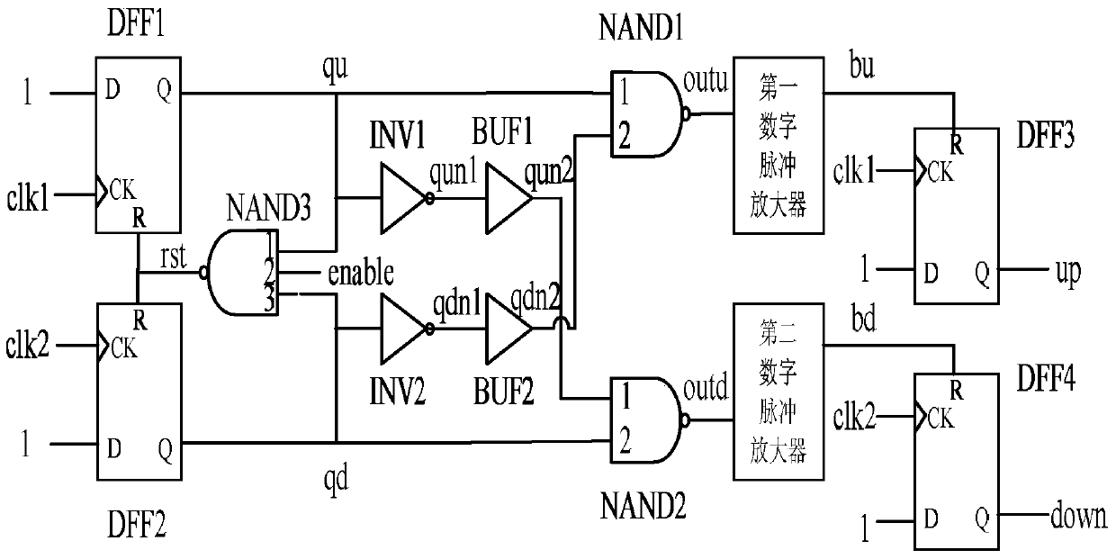
[0042] Such as figure 1 As shown, the present invention provides a kind of high precision lead-lag type digital phase detector structure, and this structure comprises:

[0043] The first signal path, the second signal path and the three-input NAND gate NAND3;

[0044] Wherein, the first signal path includes: a first D flip-flop DFF1, a first inverter INV1, a first buffer BUF1, a first NAND gate NAND1, a first digital pulse amplifier, and a third D flip-flop DFF3; The output of the first D flip-flop DFF1 is respectively connected to the first input end of the three-input NAND gate NAND3,...


PUM


Abstract

The invention provides a lead-lag digital phase discriminator structure which is composed of a first signal path, a second signal path and a three-input NAND gate. The first signal path comprises a first D-trigger, a first phase inverter, a first buffer, a first NAND gate, a first digital pulse amplifier and a third D-trigger. The second signal path comprises a second D-trigger, a second phase inverter, a second buffer, a second NAND gate, a second digital pulse amplifier and a fourth D-trigger. The third input end of the three-input NAND gate is connected with an input enabling signal, and the output end is connected with the reset ends of the first and second D-trigger. Effective time of a trigger signal is increased via appropriate additional arrangement of certain logic units and triggers so that lead-lag phase discrimination precision can be greatly enhanced.

Description

technical field [0001] The invention relates to the field of digital integrated circuits, in particular to a realization structure of a high-precision lead-lag digital phase detector. Background technique [0002] In recent years, digital phase detectors have been increasingly developed. Due to the large linear range of this type of phase detector, small output ripple, simple circuit structure, easy large-scale integration, and most of them also have the function of frequency discrimination, it has been widely used in the field of frequency synthesis. [0003] Digital phase detectors, used to compare the phase relationship of two input signals, can be divided into zero-crossing type phase detectors, flip-flop type digital phase detectors, Nyquist rate sampling type phase detectors and lead-lag type phase detectors phase device. Lead-lag digital phase detector, according to the phase relationship between the two input signals clk1 and clk2, if the phase of clk1 is ahead of ...

Claims


Application Information

Patent Timeline
Patent Type & Authority Patents(China)
IPC IPC(8): H03L7/18
Inventor 黑勇韩越乔树山
Owner SOI MICRO CO LTD
Why Eureka
Try Eureka