Clock phase discrimination method and device

A clock and phase detection technology, applied in the field of network communication

Pending Publication Date: 2020-10-30
NEW H3C TECH CO LTD
View PDF5 Cites 0 Cited by
  • Summary
  • Abstract
  • Description
  • Claims
  • Application Information

AI Technical Summary

Problems solved by technology

[0006] The invention provides a clock phase identification method and device to solve the problem

Method used


Image

  • Clock phase discrimination method and device
  • Clock phase discrimination method and device
  • Clock phase discrimination method and device

Examples


Embodiment Construction

[0026] In order to enable those skilled in the art to better understand the technical solutions in the embodiments of the present invention, and to make the above-mentioned purposes, features and advantages of the embodiments of the present invention more obvious and understandable, the following describes the technical solutions in the embodiments of the present invention in conjunction with the accompanying drawings For further detailed explanation.

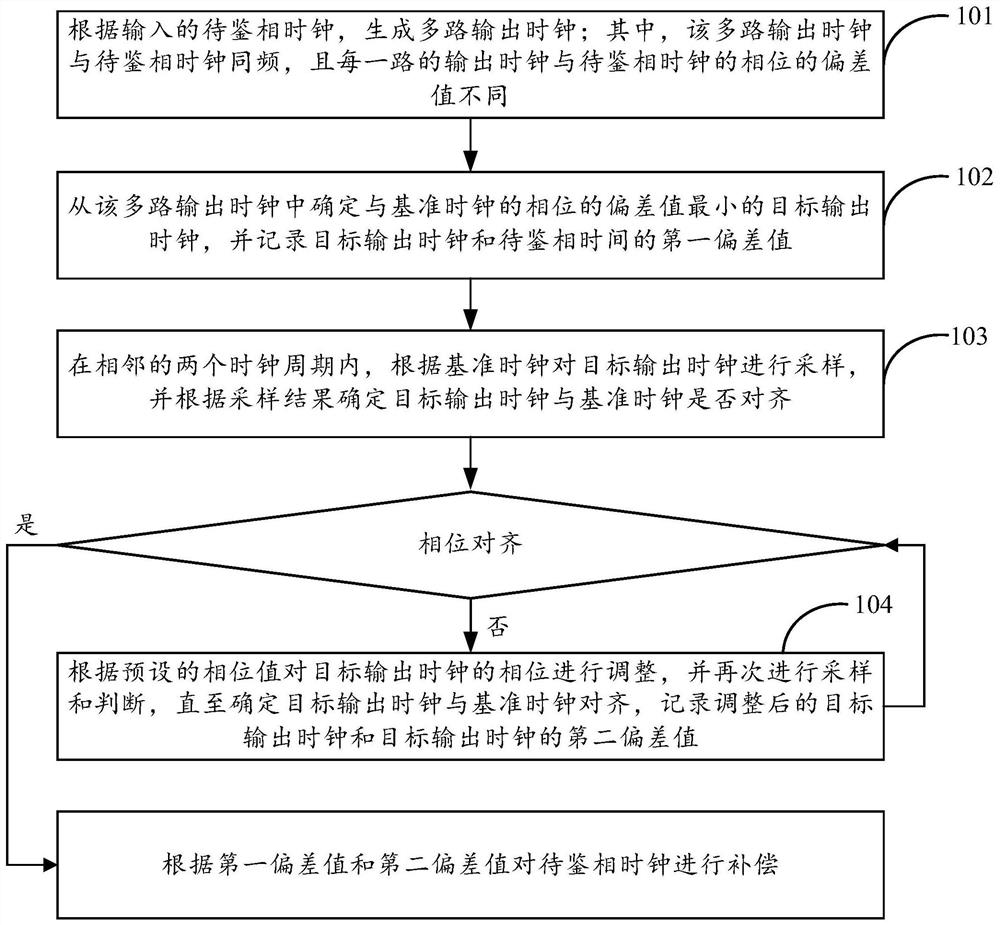
[0027] See figure 1 , is a schematic flowchart of a clock phase detection method provided by an embodiment of the present invention, wherein the clock phase detection method can be applied to FPGA, such as figure 1 As shown, the clock phase detection method may include the following steps:

[0028] Step 101 : Generate multiple output clocks according to the input clocks to be phase-detected; wherein, the multiple output clocks are of the same frequency as the clocks to be phase-detected, and the phase deviations between the ou...


PUM


Abstract

The invention provides a clock phase discrimination method and device, and the method comprises the steps: generating a plurality of output clocks, determining a target output clock with the smallestphase deviation value with a reference clock from the plurality of output clocks, and recording a first deviation value between the target output clock and a to-be-discriminated phase clock; in two adjacent clock periods, sampling the target output clock according to the reference clock, and determining whether the target output clock is aligned with the reference clock or not according to a sampling result; if the target output clock is not aligned with the reference clock, adjusting the phase of the target output clock according to a preset phase value, sampling and judging again until it isdetermined that the target output clock is aligned with the reference clock, and recording a second deviation value between the adjusted target output clock and the target output clock; and if so, compensating the to-be-discriminated phase clock according to the first deviation value and the second deviation value. By applying the embodiment of the invention, the phase discrimination precision can be improved.

Description

technical field [0001] The invention relates to the technical field of network communication, in particular to a clock phase detection method and device. Background technique [0002] Clock phase detection is mainly to identify the phase relationship between two clocks of the same source and frequency. This technology is widely used in various fields. [0003] In the communication network, many services depend on the time synchronization of the entire network, especially as the network is evolving to 5G. The bearer network needs to have functions such as large bandwidth, low latency, high-precision time synchronization, and flexible networking. Among them, ultra-high-precision time synchronization requires that the synchronization accuracy of a single device node be within 5 ns. [0004] During the processing of the 1588 time synchronization protocol, it is necessary to record the time stamp of the PTP (Precision Time Protocol, high-precision time synchronization protocol) ...

Claims


Application Information

Patent Timeline
IPC IPC(8): H03L7/085H03L7/18
CPCH03L7/085H03L7/18
Inventor 林贝贝林晖方春飞徐俊杰彭永丰
Owner NEW H3C TECH CO LTD
Why Eureka
Try Eureka