Supercharge Your Innovation With Domain-Expert AI Agents!

Filter structure for the exhaust gas from an internal combustion engine

A filter and component technology, which is applied in the field of particulate filters for internal combustion engine exhaust gas, can solve problems such as leakage structure, loss of filter structure binding force, etc.

Inactive Publication Date: 2009-02-11
SAINT GOBAIN CENT DE RES & DEVS & DETUD EUROEN
View PDF5 Cites 0 Cited by
  • Summary
  • Abstract
  • Description
  • Claims
  • Application Information

AI Technical Summary

Problems solved by technology

These cracks are accompanied by a complete loss of cohesion in the filter structure
This loss of cohesion can cause leaks and the structure must be replaced

Method used


Image

  • Filter structure for the exhaust gas from an internal combustion engine
  • Filter structure for the exhaust gas from an internal combustion engine
  • Filter structure for the exhaust gas from an internal combustion engine

Examples


Embodiment Construction

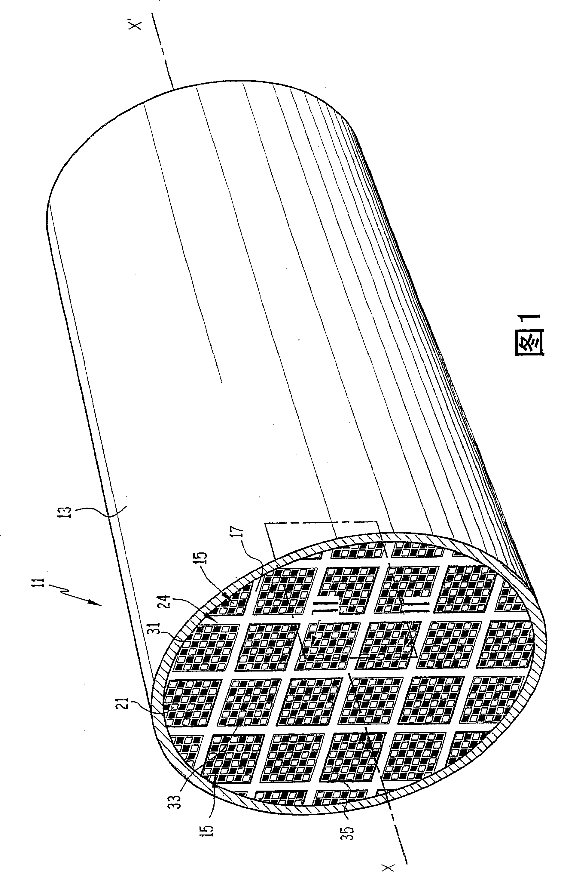
[0040] A particulate filter 11 shown in FIG. 1 is placed in an exhaust pipe 13 for discharging exhaust gas from a diesel engine of an automobile, only a part of which is shown.

[0041] The exhaust pipe 13 extends beyond the particulate filter 11 and defines a passage along which the exhaust gas flows.

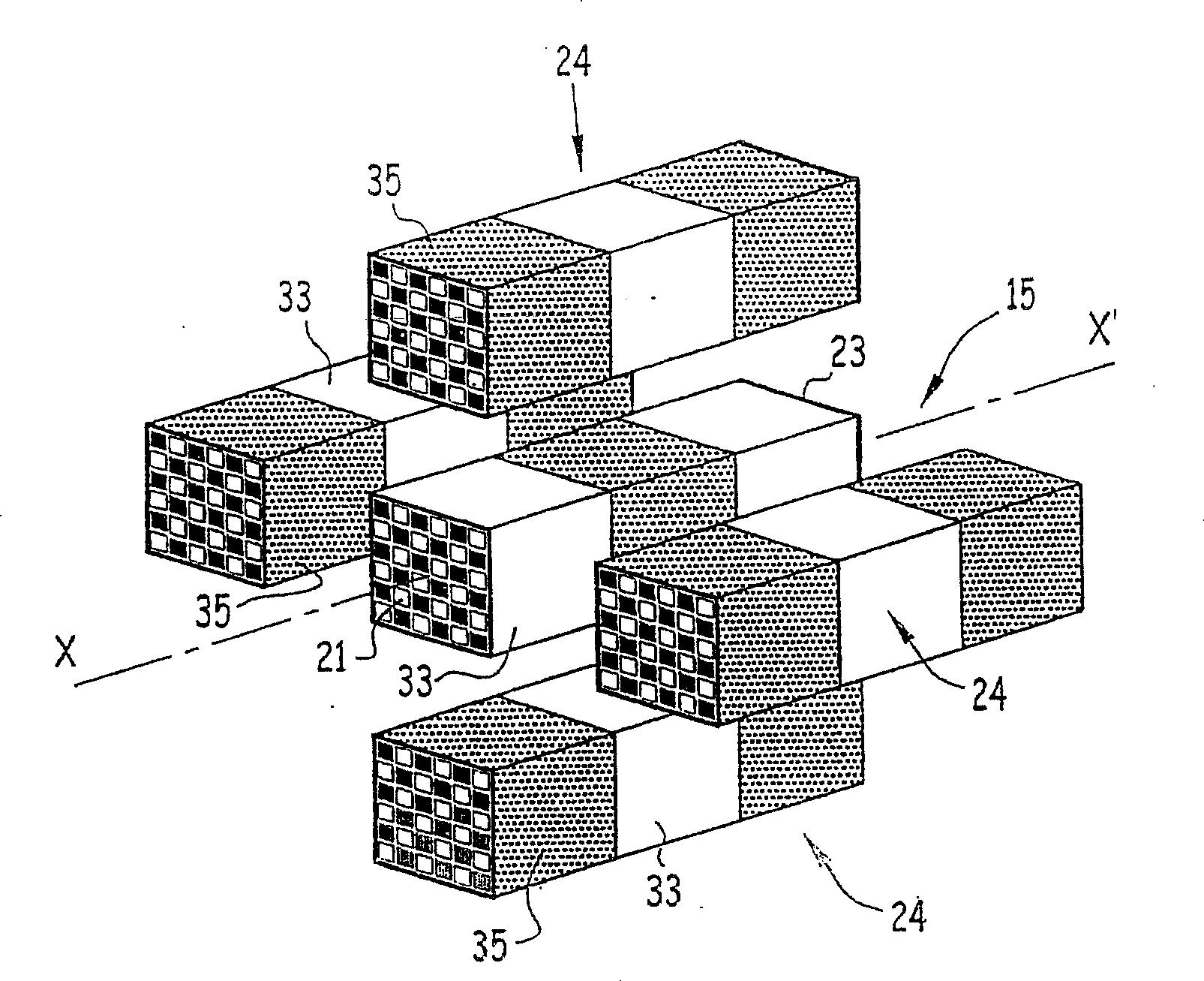
[0042] The particle filter 11 extends along the longitudinal exhaust gas flow direction XX'. It comprises a plurality of filter blocks 15 interconnected by connections 17 .

[0043] Each filter block 15 is substantially in the shape of an elongated rectangular parallelepiped extending in the longitudinal direction XX'.

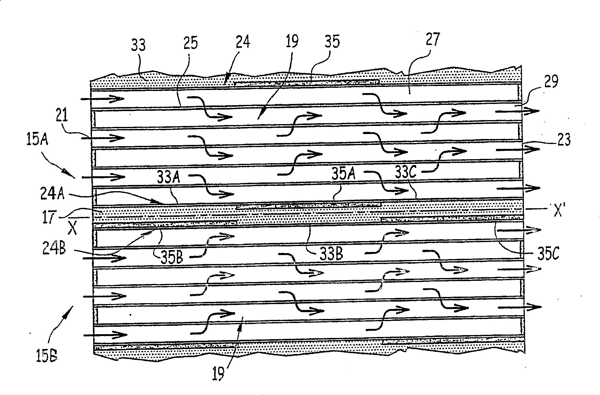
[0044] Such as figure 2 As shown, each filter block 15A, 15B includes a porous filter structure 19, an intake face 21 for receiving exhaust to be filtered, an exhaust face 23 for discharging filtered exhaust, and at least four side 24.

[0045] The porous filter structure 19 is made of monolithic filter material, in particular ceramics (cordierite or silic...


PUM

PropertyMeasurementUnit
elastic modulusaaaaaaaaaa

Abstract

The filter structure of the present invention comprises at least a first and a second filter member (15A, 15B) provided with a first and a second face (24A, 24B) placed facing each other, respectively, and connecting said faces and at said A connector (17) extending between the faces (24A, 24B). The first surface (24A) includes at least one location (33A) with strong adhesion to the connector (17) and at least one location (35A) with weak or no adhesion to the connector (17). ). These parts (33A, 35A) respectively face the part (35B) of the second surface (24B) and the said connector (17) and the second surface (24B) has strong adhesion with the said connector (17) The part (35B) is set. The structure is suitable for particle filters for exhaust gases of internal combustion engines.

Description

technical field [0001] The present invention relates to a filter structure, in particular a particulate filter for the exhaust gas of an internal combustion engine, said filter being of the type comprising: [0002] - at least a first and a second filter member provided with first and second faces arranged facing each other; and [0003] - Connectors connecting the faces together and extending between the faces. [0004] Such a structure is used in particular in devices for decontaminating the exhaust gases of internal combustion engines. Such an arrangement includes an exhaust pipe including a catalytic converter member and a particulate filter connected in series therein. Catalytic converter components are used to treat polluting emissions in the gas phase, while particulate filters are used to retain soot particles from the engine. Background technique [0005] In known structures of the type specified above (see, for example, EP-A-1 142 619), the filter element compri...

Claims


Application Information

Patent Timeline
Patent Type & Authority Patents(China)
IPC IPC(8): F01N3/022F01N3/28B01D46/00B01D46/24B01D53/94
CPCB01D46/2466B01D46/2459F01N2450/28F01N3/0222B01D2046/2496F01N3/2842B01D53/9454B01D46/2455B01D46/2451B01D46/2425Y02T10/20Y02T10/22Y02T10/12B01D46/2498B01D46/2478B01D46/2429
Inventor 塞巴斯蒂安·巴尔东樊尚·格莱兹朱利安·罗梅伊尔
Owner SAINT GOBAIN CENT DE RES & DEVS & DETUD EUROEN
Features
  • R&D
  • Intellectual Property
  • Life Sciences
  • Materials
  • Tech Scout
  • Unparalleled Data Quality
  • Higher Quality Content
  • 60% Fewer Hallucinations
Learn More