Air-valve joint of air-inflating device

An inflatable device and air nozzle technology, which is applied to the valve, valve device, functional valve type and other directions for inflation, can solve problems such as large force and difficulty, and achieve the effect of reliable action and convenient assembly.

Inactive Publication Date: 2009-02-18
王罗平
View PDF7 Cites 0 Cited by
  • Summary
  • Abstract
  • Description
  • Claims
  • Application Information

AI Technical Summary

Problems solved by technology

The known air nozzle joints must insert the mouthpieces 14, 15 into the bottom end of the housing 10, and then into the body 18. This structure makes the dimensional accuracy of the mouthpieces 14, 15 must be very high. The rubber mouthpieces 14, 15 The size of the 15 needs only to be slightly larger, and it is prone to difficulties to tuck it into the bottom of the shell
Furthermore, when the puller 27 is pulled to cause relative displacement between the body 18 and the housing 10, it is necessary to overcome the friction between the body 18 and the upper anti-leakage ring 33 and the inner wall of the housing 10, which requires a relatively large force.

Method used


Image

  • Air-valve joint of air-inflating device
  • Air-valve joint of air-inflating device
  • Air-valve joint of air-inflating device

Examples


Embodiment Construction

[0016] In order to illustrate the structure and achieved effects of the present invention in detail, a preferred embodiment is given and described with accompanying drawings.

[0017] The embodiment of the present invention is illustrated by a double-air nozzle joint, and its structure can also be applied to a single-air nozzle joint.

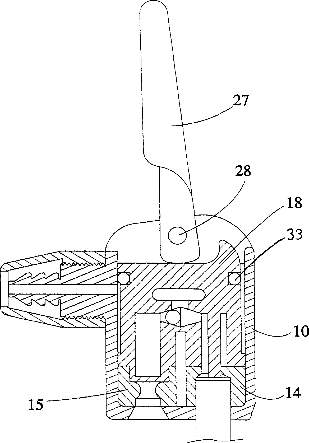
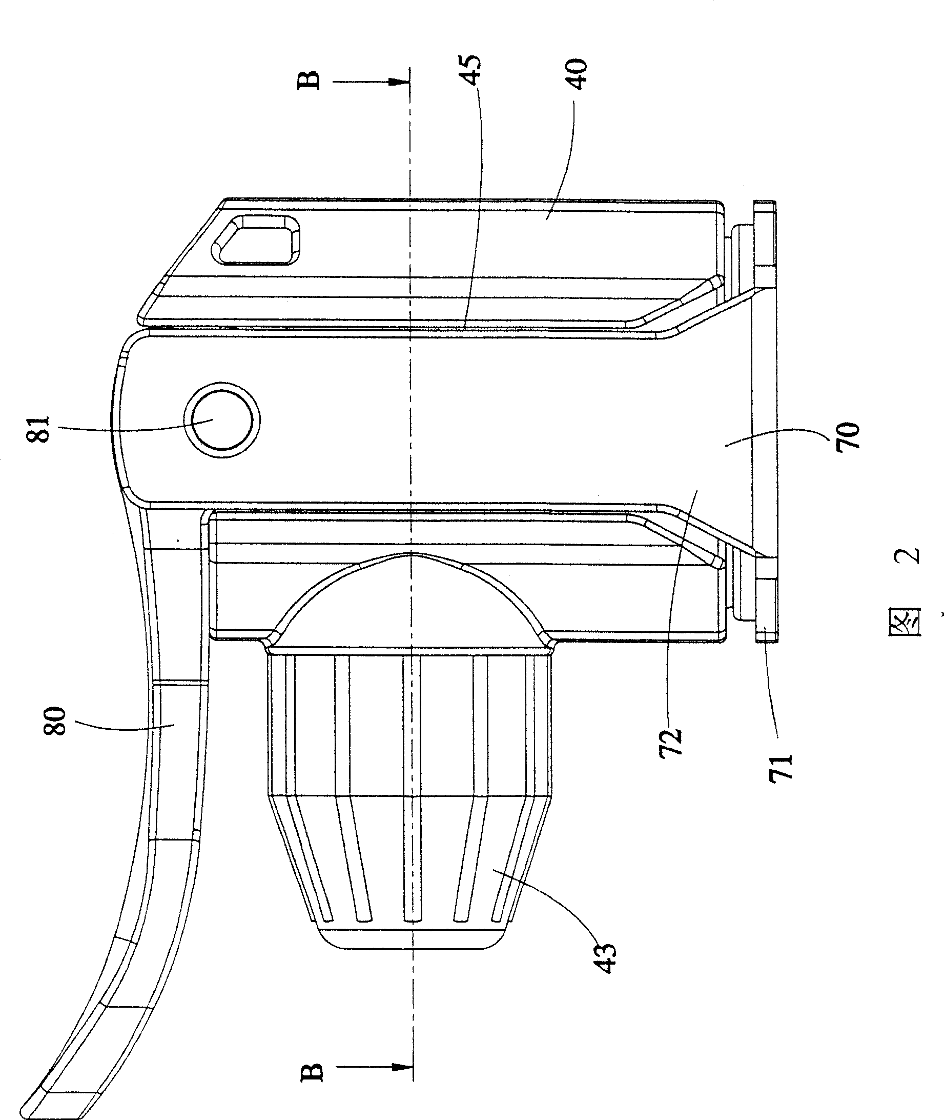
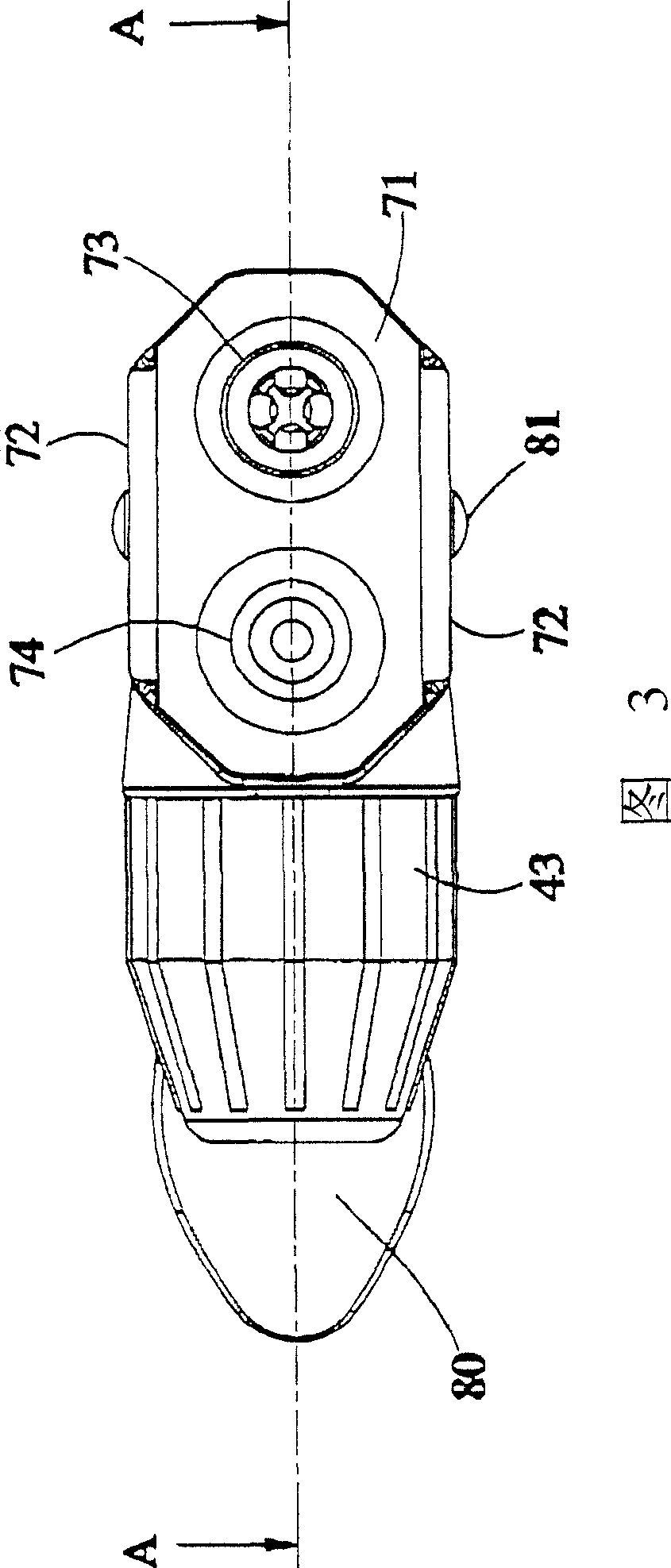
[0018] As shown in Figure 2 to Figure 5, the air nozzle connector in this example includes:

[0019] A housing 40, which has an air inlet channel 41, communicates with the outlet flow channel (not shown in the figure) of the inflator, and in this embodiment, a plug joint 42 is provided at the outer end of the air inlet channel 41 for a flexible pipe (shown in the figure). (not shown in the figure), and then screwed and locked on the preset thread 44 of the housing 40 with a bolt cover 43. This type can be used for floor pumps (FloorPump) and other inflatable devices with inflatable hoses. The housing 40 can also be directly connected to the pu...


PUM


Abstract

A nozzle joint of an air charging device comprises a shell with an air inlet channel, a least a nozzle component inside the shell and connected with the air inlet channel, the nozzle component composed of a spring sleeve, a hold part with a bottom, extending two parallel arm from the bottom, the shell contained between two arms of the holding parts, whose bottom corresponding to each nozzle part having a through hole, a banner part setting between holder two arms through a pin, with two end surfaces with one of it having smaller distance to the pivot center than the other. When the first end surface contacts with the shell, spring component of the nozzle sleeve at loose ends, and when the second end surface contacts with the shell, bottom of the holder part attaches to the shell and spring sleeve of the squeeze nozzle component deformed. It is convenient assembly, solid action and labor saving.

Description

technical field [0001] The invention relates to an inflatable device, in particular to a structure of an air nozzle joint of the inflatable device. Background technique [0002] Such as figure 1 As shown, it is the previous case of the Taiwan No. 135498 patent (US 5,960,815). The conventional air pump nozzle connector includes a housing 10, a body 18 and two mouthpieces 14, 15 accommodated in the housing 10, and a The triggering member 27 is disposed on the housing with a pin 28 . What this patent discloses is a structure with double air nozzle joints, and the conventional single air nozzle joint structure only needs to omit one joint and the automatic switching valve therein. The known air nozzle joints must insert the mouthpieces 14, 15 into the bottom end of the housing 10, and then into the body 18. This structure makes the dimensional accuracy of the mouthpieces 14, 15 must be very high. The rubber mouthpieces 14, 15 The size of the 15 needs only to be slightly large...

Claims


Application Information

Patent Timeline
Patent Type & Authority Patents(China)
IPC IPC(8): F16K24/06
Inventor 王罗平
Owner 王罗平
Why Eureka
Try Eureka