An optical fiber

A technology of optical fiber and optical waveguide, which is applied in cladding optical fiber, optical waveguide and light guide, etc., can solve the problems of large insertion loss, increased cost, poor control of refractive index distribution, etc., and achieve large dispersion compensation per unit length and flexible design Effect

Inactive Publication Date: 2009-03-04
UNIV OF ELECTRONICS SCI & TECH OF CHINA
View PDF2 Cites 1 Cited by
  • Summary
  • Abstract
  • Description
  • Claims
  • Application Information

AI Technical Summary

Problems solved by technology

[0007] Although the dispersion compensating fiber (DCF) compensation method has the above advantages, it should be noted that the compensation amount per unit length of DCF is low, and the dispersion compensation value of DCF per kilometer is generally on the order of hundreds of ps / nm
In addition, the insertion loss of DCF is relatively large. After dispersion compensation, an optical amplifier is required to compensate the loss, which increases the cost.
In addition, compared with standard optical fibers, DCF has a thinner core diameter and a larger refractive index difference, so the refractive index distribution is not easy to control, and the production is more difficult.

Method used


Image

  • An optical fiber
  • An optical fiber
  • An optical fiber

Examples


Embodiment 1

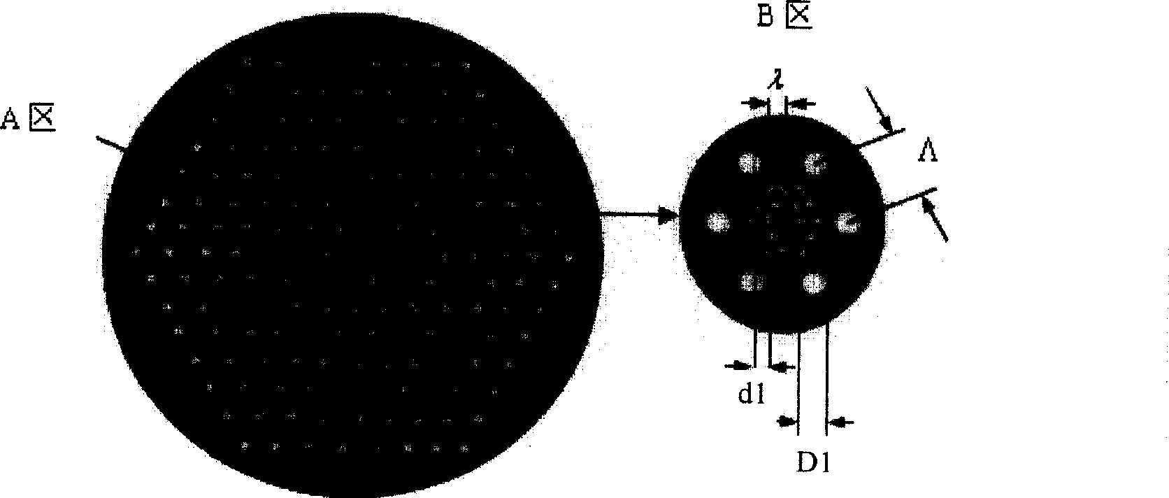
[0050] Referring to the photonic crystal fiber structure of solid light guide, it is composed of quartz and air holes in the cladding, which can be regarded as the quartz in the center surrounded by air holes. In view of this, the present invention refers to such a structure as a light guide unit, the solid part in the center is called a central optical waveguide area, and the peripheral air hole and its surrounding areas are called an outer field area. Such as Figure 4 As shown, the central optical waveguide area is inside the middle ring, and the outer area with air holes is the outer field area.

[0051] see image 3 . This embodiment includes a first light guide unit and a second light guide unit, and the second light guide unit is distributed in the outer field area of ​​the first light guide unit and is surrounded by air holes of the first light guide unit. The structures of the first and second light guide units are arranged in the manner of photonic crystal fiber, ...


PUM


Abstract

Optical fiber mainly involves optical fiber communications technology. The invention includes first - and second-beam unit, the second unit distributes in the first's outside field, and was surrounded by the first unit stomata. The beneficial effect of invention is having a great unit length of dispersion compensation, and flexible design of the slope of the dispersion compensation. PCF clad special structure can be changed by the designers cladding air holes parameters of the structure to have the flexibility to change the refractive index of optical fiber cross-sectional distribution, designed to have different dispersion nature fiber.

Description

technical field [0001] The invention relates to optical fiber communication technology. Background technique [0002] In optical fiber communication, there are different degrees of dispersion problems. Dispersion refers to the phenomenon of light pulse broadening caused by the group delay difference of light waves of different frequencies or different modes in the fiber. Since the optical fiber digital communication transmits a series of optical pulse codes, when the optical pulse is transmitted along the optical fiber, the dispersion makes the optical signal pulse broaden, causing a part of adjacent pulses to overlap each other, so that two adjacent pulses cannot be correctly identified by the receiving device As a result, system errors are caused and communication quality is affected. In order to limit inter-symbol interference, the pulse broadening caused by dispersion must be limited within a certain range. When the optical signal pulse broadening caused by dispersion ...

Claims


Application Information

Patent Timeline
Patent Type & Authority Patents(China)
IPC IPC(8): G02B6/02
Inventor 姜海明王文丹谢康王亚非
Owner UNIV OF ELECTRONICS SCI & TECH OF CHINA
Why Eureka
Try Eureka