Arc quenching system

An arc extinguishing device and arc guiding technology, which is applied to emergency protection devices, parts of protective switches, electrical components, etc., can solve problems such as increasing power consumption and increasing the temperature rise of line protection switches

Active Publication Date: 2009-03-11
SIEMENS AG
View PDF6 Cites 4 Cited by
  • Summary
  • Abstract
  • Description
  • Claims
  • Application Information

AI Technical Summary

Problems solved by technology

However, the arc blowing circuit is continuously flowed by the working current of a switch circuit, which will increase the power consumption, thereby causing the temperature rise of the line protection switch to increase

Method used


Image

  • Arc quenching system
  • Arc quenching system

Examples


Embodiment Construction

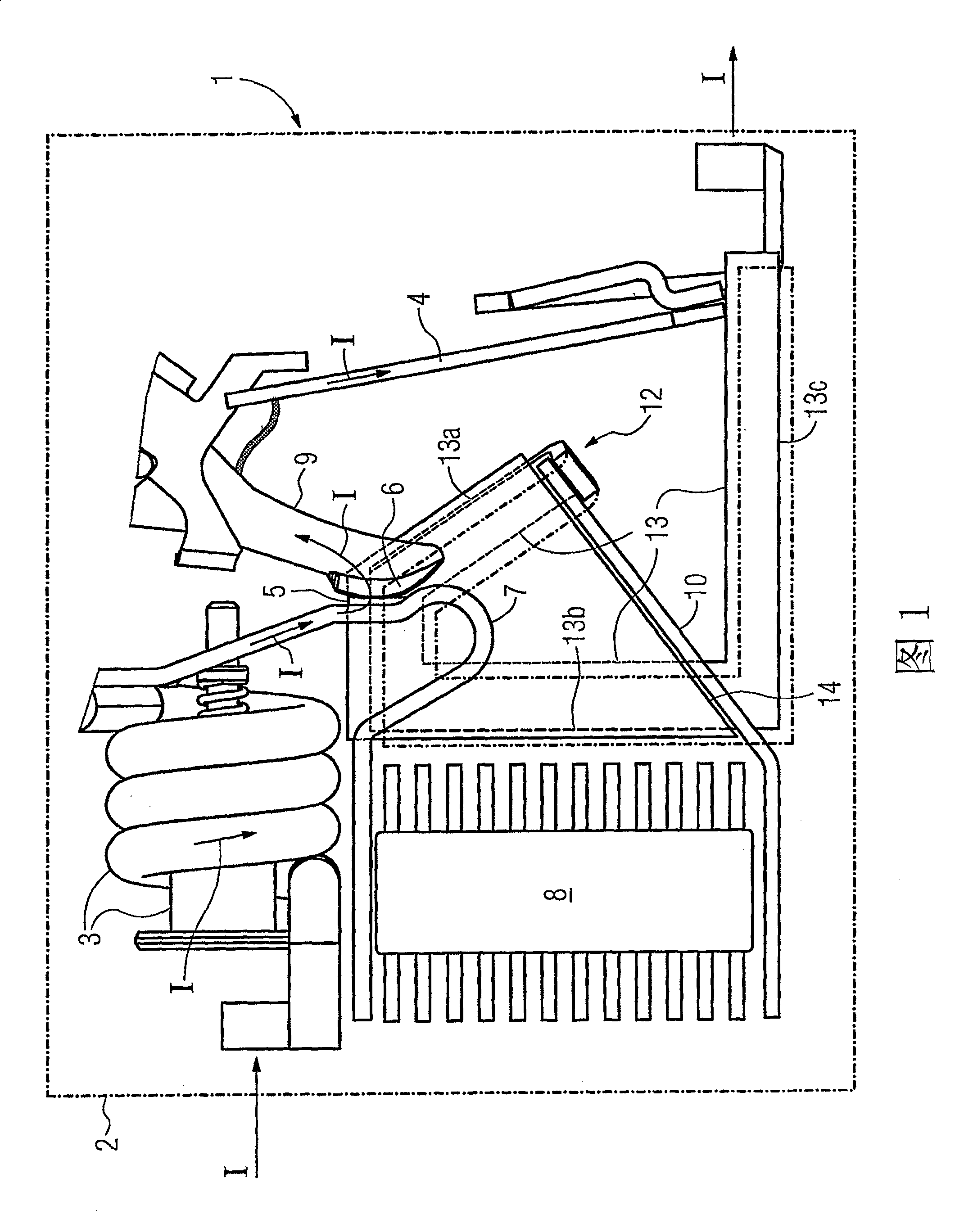
[0023] FIG. 1 shows a section through a switchgear 1 with an arc quenching device, said switchgear having a housing 2 shown here in diagrammatic form. In this embodiment, the switchgear 1 is implemented as a line protection switch, which, in addition to an electromagnetic release 3, also has a thermal release 4 and a pair comprising a fixed contact 5 and a moving contact 6 in the Inside switch contacts. The static contact 5 is fixed on an arc-guiding track 7 which functions as a contact seat, and the arc-guiding track 7 also has a conductive connection with a coil of the electromagnetic release 3 . The coil itself leads to a connection terminal which is shown here in diagrammatic form. The free end of the arc guide track 7 passes through an adjacent magnetic yoke and leads into an arc extinguishing chamber 8 . The part of the arc-guiding track 7 behind the fixed contact 5 leading to the arc-extinguishing chamber 8 is designed as an ear. The movable contact 6 is fastened to ...


PUM


Abstract

The aim of the invention is to create an arc quenching system for a switching device (1), which ensures low heat build-up and fast quenching of an arc (11) using simple means. Said aim is achieved by providing a current conducting path (13) which comprises an electrically conducting passage to an additional arc guide rail (10) so as to form a conductor loop (10, 13) and is electrically insulated relative to a pair of switching contacts (5, 6). The conductor loop (10,13) is not connected to the pair of switching contacts (5, 6) while being arranged in the area of an interrupter chamber (12) such that a current (I) which drives the arc (11) into the arcing chamber (8) is conducted via the current conducting path (13) when the arc (11) commutates from one of the switching contacts (5; 6) to the additional arc guide rail (10).

Description

technical field [0001] The invention relates to an arc extinguishing device for a switchgear. Background technique [0002] This type of arc extinguishing device is used to interrupt or extinguish the arc generated when a pair of current-carrying contacts is disconnected. When the contacts are separated from each other, the current flows in a correspondingly smaller contact area, so that the temperature in this area gradually increases. A moment before the contact is separated, a melting bridge will be generated, and the melting bridge will eventually be broken when the current is small; when the current is large, the melting bridge will evaporate. Therefore, the current can only continue to flow through an arc in the form of a conductive plasma column. [0003] The type and magnitude of the switching current will have an effect on the strength of this arc. When a short-circuit occurs in a circuit protected by a circuit breaker, for example a short-circuit current of up t...

Claims


Application Information

Patent Timeline
Patent Type & Authority Patents(China)
IPC IPC(8): H01H73/18H01H9/44H01H71/12
CPCH01H9/44H01H73/18H01H71/121
Inventor 冈瑟·埃克特保罗·赫马沃尔夫冈·莱特尔
Owner SIEMENS AG
Why Eureka
Try Eureka