
Hair styling appliance

A hair straightener and hair technology, which can be applied to hair brushes, hair curlers, hairdressing equipment, etc., can solve the problems of prolonging hair straightening time, increasing power consumption, and not lasting hair straightening effect.

Inactive Publication Date: 2009-04-01
MATSUSHITA ELECTRIC WORKS LTD
View PDF6 Cites 0 Cited by
  • Summary
  • Abstract
  • Description
  • Claims
  • Application Information

AI Technical Summary

Problems solved by technology

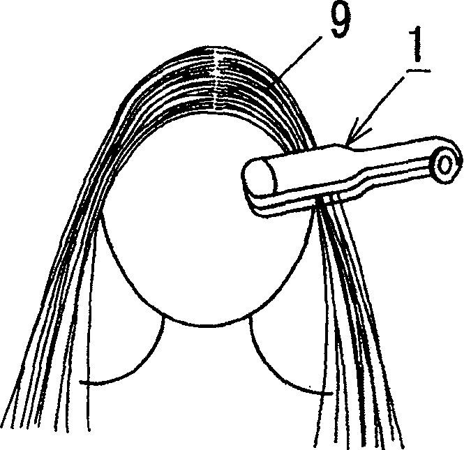
However, in these cases, such as Figure 7 As shown, the hair 9 between the vibrating part 3 and the backing part 7 is spread laterally due to the ultrasonic vibration, which causes the hair styling effect to be unsustainable, prolongs the hair styling time, increases power consumption, etc.

Method used


Image

  • Hair styling appliance
  • Hair styling appliance
  • Hair styling appliance

Examples


Embodiment Construction

[0034] Figure 8 A first embodiment according to the invention, namely a hair styler 11 is shown. The hair styler 11 includes: a first arm 12 formed in a long bar shape or a plate shape; and a second arm 16 formed in a long bar shape or a plate shape. The first arm 12 is divided into a handle end 12a and a hair styling end 12b, and the second arm 16 is likewise divided into a handle end 16a and a hair styling end 16b. The top ends of the handle end 12a of the first arm 12 and the handle end 16a of the second arm 16 are secured by a hinge so that the first arm 12 and the second arm 16 can pivot about the top ends.

[0035] The hair styling end 12b of the first arm 12 is provided with a vibrating portion 13 composed of a vibrator 14 and an ultrasonic vibration guide 15, and the hair styling end 16b of the second arm 16 is provided with a backing portion 17 such as a flat plate or the like. That is, the hair styler 11 includes a vibrating part 13 and a backing part 17 between w...


PUM


Abstract

A hair styling appliance is provided in order to prevent hair between a vibrating portion and a backing portion from spreading widely by ultrasonic vibration of the vibrating portion. The vibrating portion comprises a vibrator and an ultrasonic vibration horn. The horn has a contact end brought into contact with the hair and a mounting end on which the vibrator is mounted, and amplifies and transmits the ultrasonic vibration of the vibrator mounted on the mounting end to the contact end. The horn is formed so that amplitude of the ultrasonic vibration in both sides of the center of the contact end is larger than that in the center.

Description

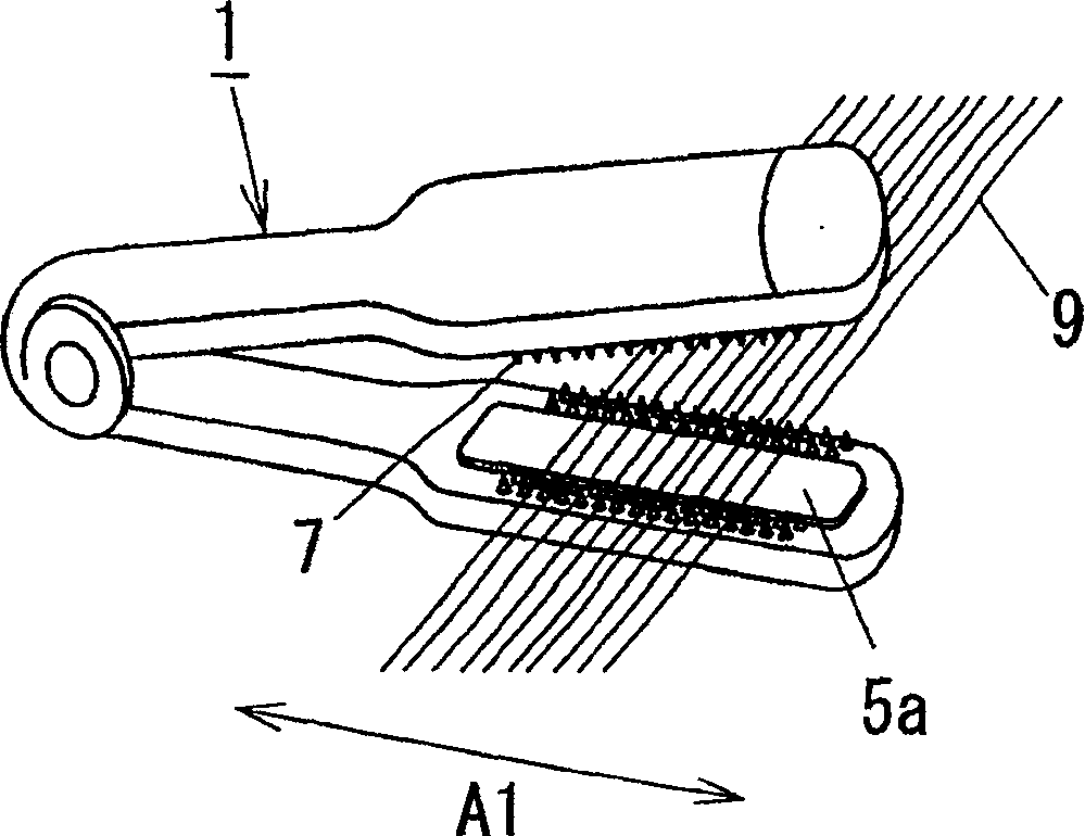
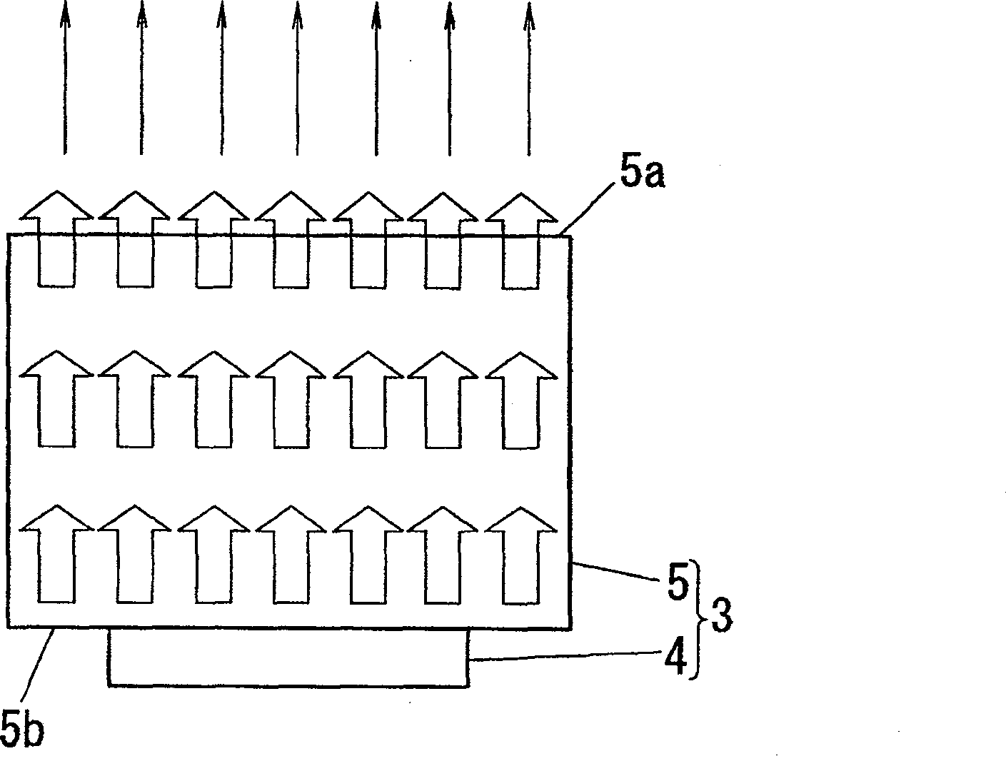
technical field [0001] The present invention relates to a hair styling appliance for styling hair by using ultrasonic vibration. Background technique [0002] Such as figure 1 and figure 2 As shown, the prior art hair styler 1 described in Japanese Patent Laying-Open No. 2002-282788 is the above-mentioned hair styler. Such as Figure 1 to Figure 3 As shown, the hair styler 1 includes a vibrating portion 3 and a backing portion 7, between the vibrating portion 3 and the backing portion 7 hair 9 is placed, and the vibrating portion 3 and the backing portion 7 are composed of The user closes and separates (opens). The vibration section 3 includes a vibrator 4 that generates ultrasonic vibrations and an ultrasonic vibration horn 5 having a contact end 5 a that contacts the hair 9 and a mounting end 5 b that mounts the vibrator 4 . The guide plate 5 amplifies and transmits the ultrasonic vibration of the vibrator 4 mounted on the mounting end 5b to the contact end 5a. Ultr...

Claims


Application Information

Patent Timeline
Patent Type & Authority Patents(China)
IPC IPC(8): A45D7/00
CPCA46B2200/3093A45D19/02A45D19/16A46B2200/104A45D24/30A45D34/04B06B3/00A45D1/02A45D2/001A45D2200/207A45D2200/1054
Inventor 今井健之内梨荣
Owner MATSUSHITA ELECTRIC WORKS LTD
Learn More