
A light-emitting diode chip array and display panel

A technology of light-emitting diodes and chip arrays, applied in semiconductor devices, electrical components, circuits, etc., can solve the problems of small display pixels and short-circuiting of adjacent LED chip electrodes.

Active Publication Date: 2021-05-04
CHENGDU VISTAR OPTEOLECTRONICS CO LTD
View PDF5 Cites 0 Cited by
  • Summary
  • Abstract
  • Description
  • Claims
  • Application Information

AI Technical Summary

Problems solved by technology

Due to the high requirements for the number of pixels (Pixels Per Inch, PPI) of the Micro-LED display panel, the display pixels are usually small, and the distance between adjacent LED chips is very small. Therefore, the existing LED chip array is bonded to the driving backplane ( During bonding), there is a problem that the electrodes between adjacent LED chips are prone to short circuit

Method used


Image

  • A light-emitting diode chip array and display panel
  • A light-emitting diode chip array and display panel
  • A light-emitting diode chip array and display panel

Examples


Embodiment Construction

[0033] The present invention will be further described in detail below in conjunction with the accompanying drawings and embodiments. It should be understood that the specific embodiments described here are only used to explain the present invention, but not to limit the present invention. In addition, it should be noted that, for the convenience of description, only some structures related to the present invention are shown in the drawings but not all structures.

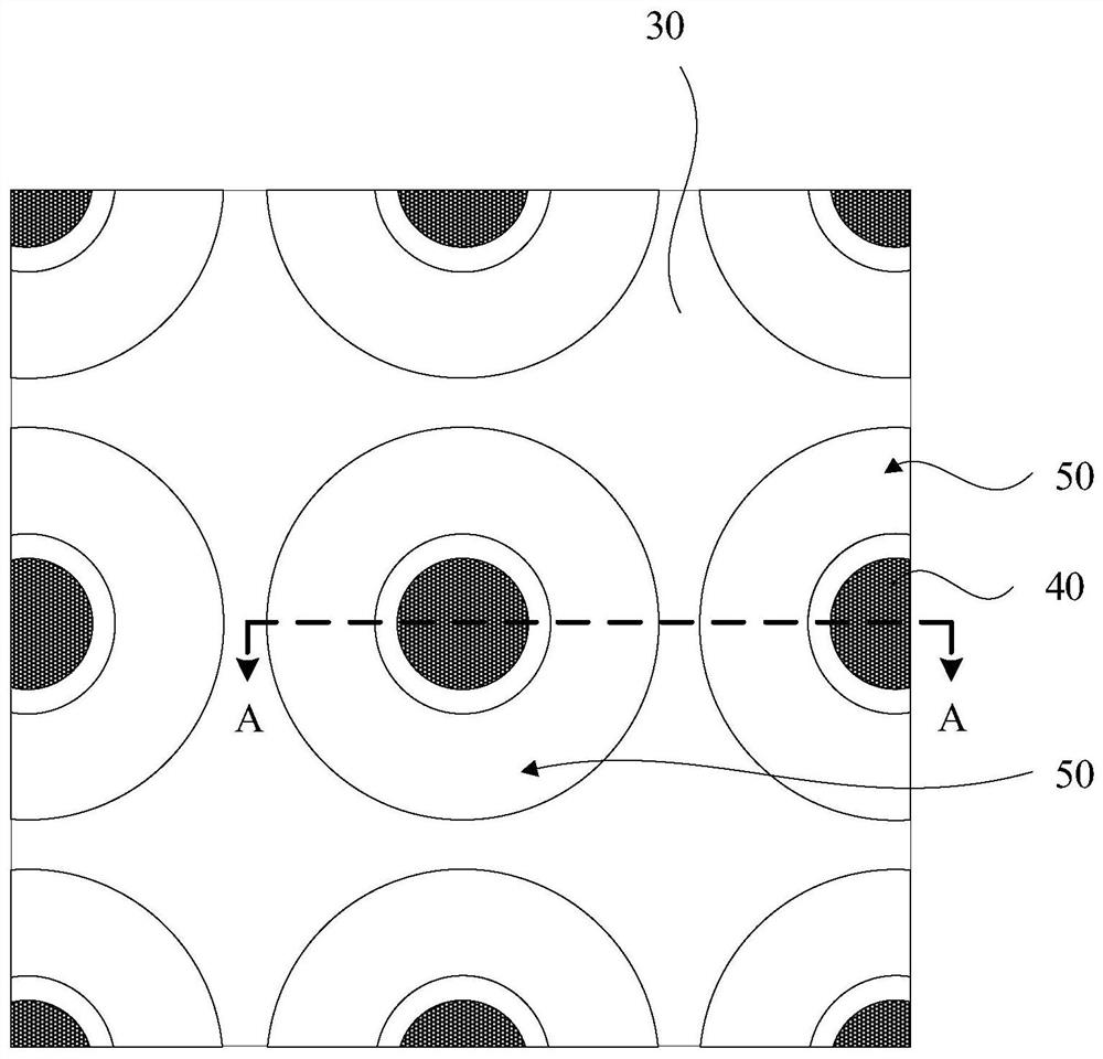
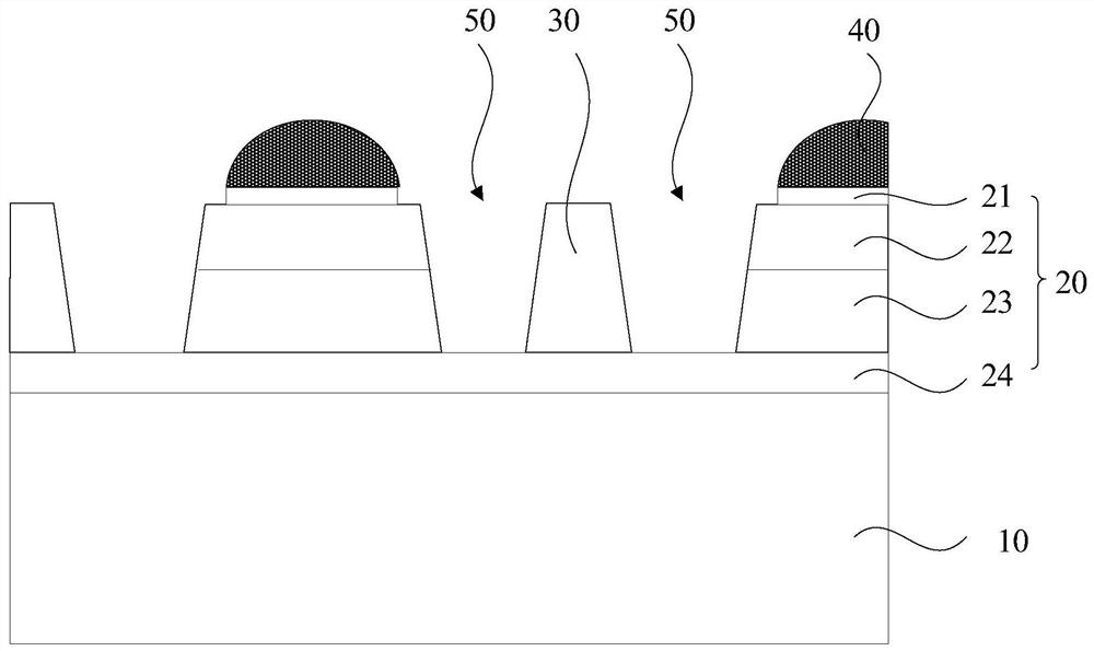
[0034] figure 1 It is a schematic top view structural diagram of a light emitting diode chip array provided by an embodiment of the present invention, figure 2 for along figure 1 Schematic diagram of the cross-sectional structure of A-A. see figure 1 and figure 2 , the light emitting diode chip array includes: a substrate 10 , a plurality of light emitting diode chips 20 , isolation walls 30 and solder joints 40 . A plurality of LED chips 20 and isolation walls 30 are located on the substrate 10 , and the L...


PUM


Abstract

The embodiment of the invention discloses a light emitting diode chip array and a display panel. The light-emitting diode chip array includes: a substrate; a plurality of light-emitting diodes located on the substrate, the light-emitting diodes include a first electrode; an isolation wall, a groove is formed between the isolation wall and the light-emitting diodes; The welding spot is located on the first electrode. The embodiment of the present invention realizes the effect of avoiding the electrode short circuit between adjacent LED chips, and improves the yield rate of bonding; and the structure of the light emitting diode chip array provided by the embodiment of the present invention is simple, and the process is simple and easy, which is beneficial to improve Process feasibility of LED chip array and reliability of display panel.

Description

technical field [0001] The embodiments of the present invention relate to the field of display technology, and in particular to a light emitting diode chip array and a display panel. Background technique [0002] Micro Light Emitting Diode (micro-LED / μLED) display panels integrate light emitting diode (Light Emitting Diode, LED) chips with a size of less than 100 microns on a substrate as display pixels to realize image display. Each display pixel can be addressed and individually driven to light up, so the Micro-LED display panel is a self-illuminating display panel. [0003] In the prior art, a Micro-LED display panel includes an LED chip array and a driving backplane. Due to the high requirements for the number of pixels (Pixels Per Inch, PPI) of the Micro-LED display panel, the display pixels are usually small, and the distance between adjacent LED chips is very small. Therefore, the existing LED chip array is bonded to the driving backplane ( When bonding), there is a...

Claims


Application Information

Patent Timeline
Patent Type & Authority Patents(China)
IPC IPC(8): H01L27/15
CPCH01L27/156H01L33/005H01L2933/0008
Inventor 郭恩卿王程功田文亚盖翠丽李之升
Owner CHENGDU VISTAR OPTEOLECTRONICS CO LTD
Learn More