Locking ring

A technology for snap rings and ring parts, which is applied in the field of snap rings, and can solve the problems of unfavorable insertion and unsatisfactory alignment of journals

Active Publication Date: 2009-04-01
轴造型工程公司
View PDF8 Cites 1 Cited by
  • Summary
  • Abstract
  • Description
  • Claims
  • Application Information

AI Technical Summary

Problems solved by technology

[0003] The problem with this type of locking ring is that, after installation, it is not perfectly centered in the outer groove of the journal, so when in the ring it is necessary to place the journal with the fitted locking ring into the ring Its insertion into the ring is unfavorable due to large chamfers or bevels of the end faces in the internal bore of the part or special auxiliary devices

Method used


Image

  • Locking ring
  • Locking ring
  • Locking ring

Examples


Embodiment Construction

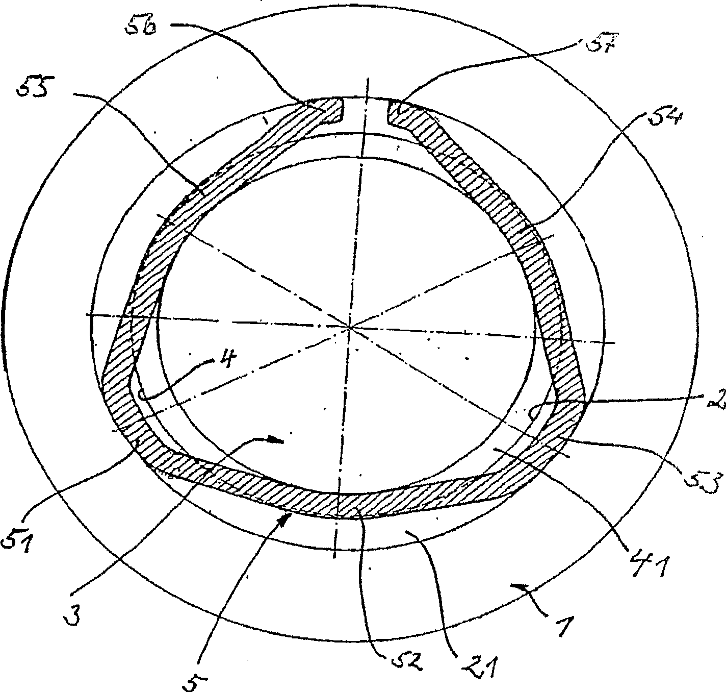
[0018] exist figure 1 Among them, the annular ring part is represented by 1, the shaft part is represented by 3, and the snap ring of the present invention is represented by 5.

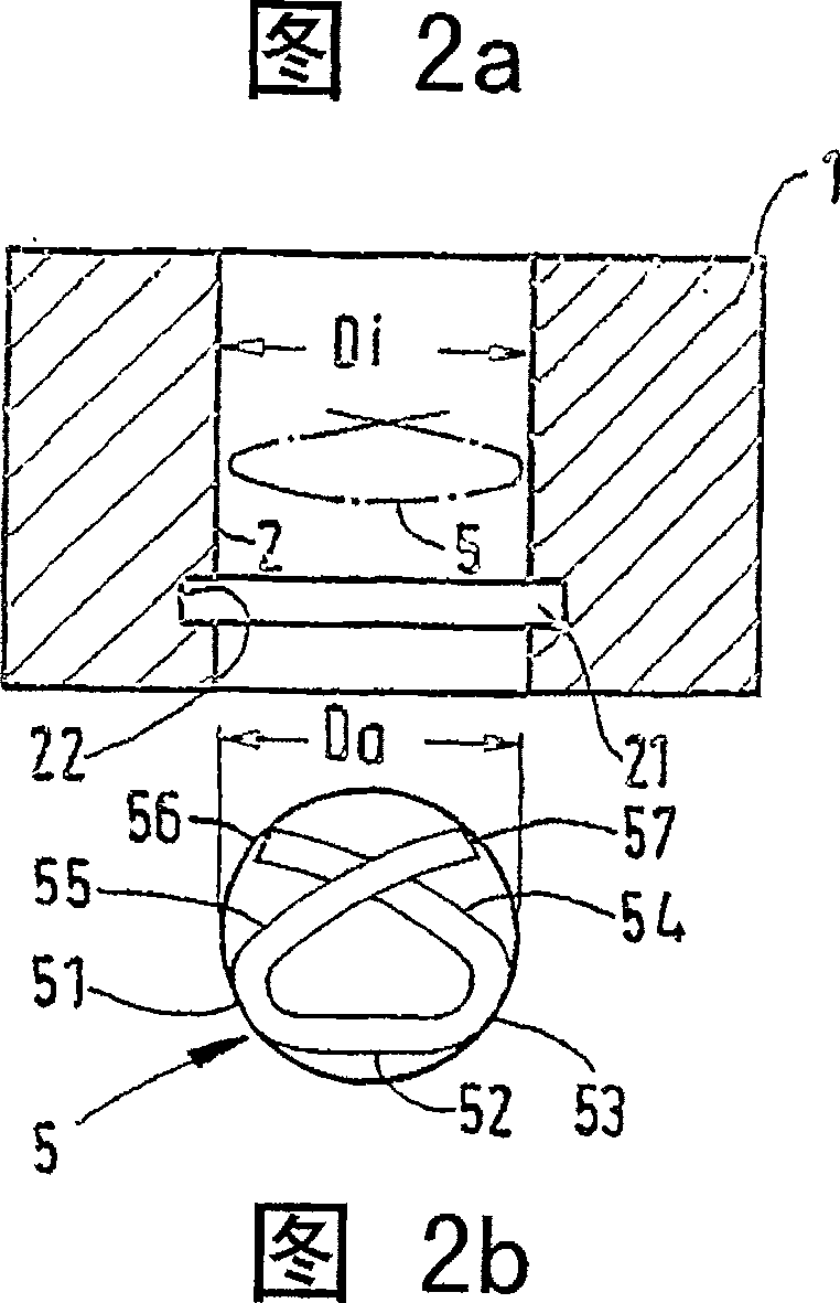
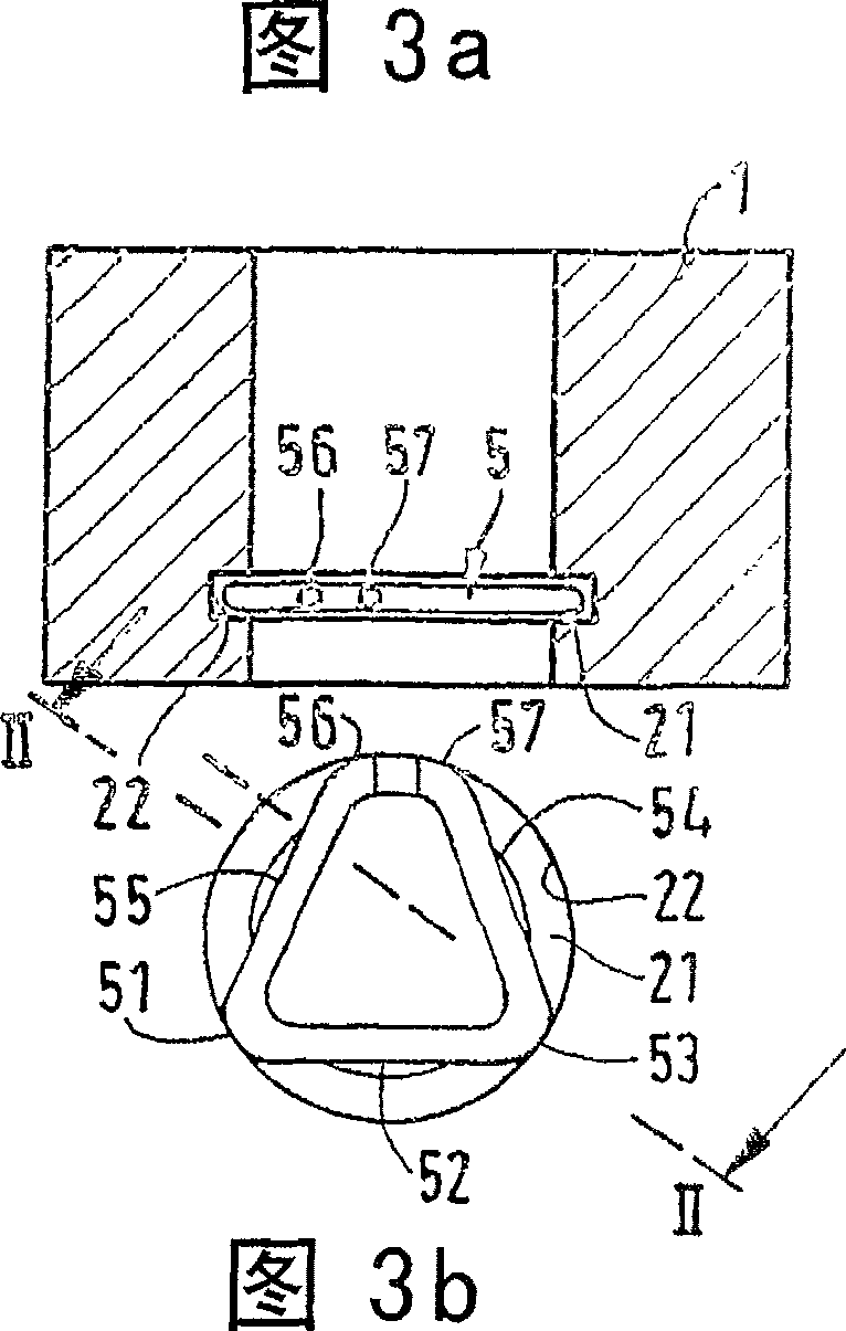
[0019] The annular ring part 1 surrounds a circular inner bore 2 in which an annular inner groove 21 is arranged. An annular outer circumferential groove 41 is provided on the outer circumference 4 of the shaft part 3 .

[0020] According to a preferred embodiment, the safety washer 5 basically comprises a base 52 and laterally arranged legs 54, 55 which together have an approximately triangular shape, wherein preferably the legs 54 and 55 The opposite free ends 57 and 58 are spaced apart from each other in the circumferential direction. The base 52 is connected to the leg 54 via a preferably rounded corner region 53 . Accordingly, the base 52 is connected to the leg 55 via a preferably rounded corner region 51 . Particularly preferably, the shape is a substantially equilateral triangle, wherein t...


PUM


Abstract

The invention relates to a locking ring for axially fixing a shaft part (3) in a ring part (1). The locking ring (5) has first partial areas (56, 57, 51, 53) which engage in the inner groove (21) after resiliently pressing together the locking ring (5) so that it can be placed in the inner opening (21) of the ring part (1), pushing the safety ring (5) into the area of the inner groove (4) and releasing and resiliently placing the locking ring (5). The locking ring also has second partial areas (52, 54, 55) that project from the inner groove (21) once the safety ring (5) has been placed in the inner groove (21) and which are resiliently pushed outward in a phase (7) of the shaft part (3) which has been pushed into the inner opening (2) so that the safety ring (5) can slide on the periphery of the shaft part (3) until it reaches the area of the peripheral groove (4) and the second partial areas (52, 54, 55) resiliently snap onto said peripheral groove.

Description

technical field [0001] The invention relates to a snap ring. Background technique [0002] Such snap rings are known. For example, a locking ring is disclosed in DE4109481C2, which uses the ring opening to snap elastically into an inner groove provided with groove slopes or a turned annular groove in an inner hole of the ring, and in a An outer groove provided with a radial free space for assembly is used on the journal to form a releasable snap-fit ​​connection between the ring and the journal. For assembly, the locking ring is broken apart and pushed onto the journal until it snaps into the outer groove of the journal. Next, the journal with the assembled locking ring is inserted into the inner bore of the ring part provided with the bevel of the end face, wherein the locking ring is compressed and springs out radially when it reaches the inner groove of the ring part, so that The journal and the ring are axially locked against each other. [0003] The problem with thi...

Claims


Application Information

Patent Timeline
Patent Type & Authority Patents(China)
IPC IPC(8): F16B21/18
CPCF16B21/186
Inventor 维尔纳·雅各布
Owner 轴造型工程公司
Why Eureka
Try Eureka