Multi-wavelength light-emitting bipolar body and light-emitting wafter structure

A technology of light-emitting diodes and light-emitting chips, which is applied in the direction of semiconductor devices, electrical components, circuits, etc., can solve the problem of inability to accurately control the light color quality, composition ratio, coating range and coating weight of light-emitting diodes, Reduce the brightness performance effect of light-emitting diodes and other issues

Inactive Publication Date: 2009-04-08
TAIWAN OASIS TECH CO LTD
View PDF4 Cites 0 Cited by
  • Summary
  • Abstract
  • Description
  • Claims
  • Application Information

AI Technical Summary

Problems solved by technology

[0004] However, such an approach will embed part of the bottom of the light-emitting chip 20 into the solid crystal material 40, thereby reducing the brightness performance effect of the overall light-emitting diode; moreover, although fluorescent materials can be mixed into the solid crystal material 40, The light source of the light-emitting chip 20 can be combined with the wavelength of the fluorescent material to obtain the desired light color, but because the composition ratio, coating range, and coating amount of the crystal-fixing material 40 are not easy to control, the overall light-emitting diode cannot be accurately controlled The quality of light and color presented

Method used


Image

  • Multi-wavelength light-emitting bipolar body and light-emitting wafter structure
  • Multi-wavelength light-emitting bipolar body and light-emitting wafter structure
  • Multi-wavelength light-emitting bipolar body and light-emitting wafter structure

Examples


Embodiment Construction

[0024] In order to make the composition and implementation of the present invention clear to your examiner, the description is as follows in conjunction with the drawings:

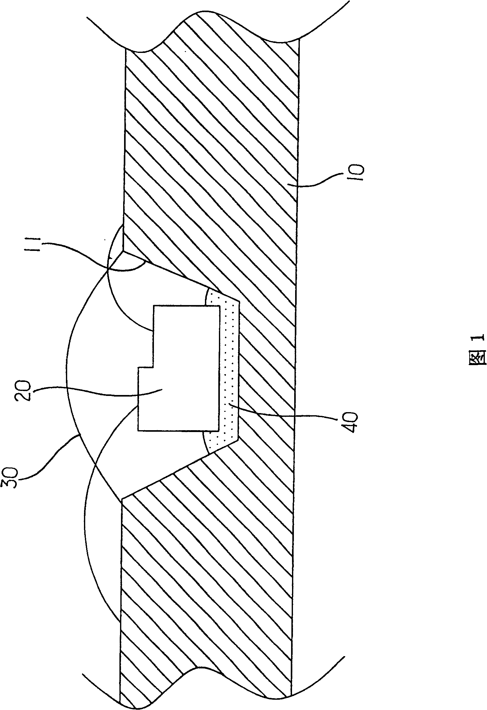
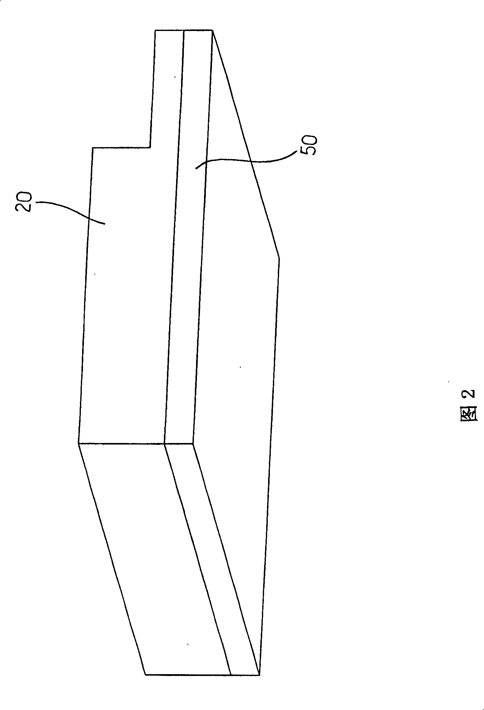
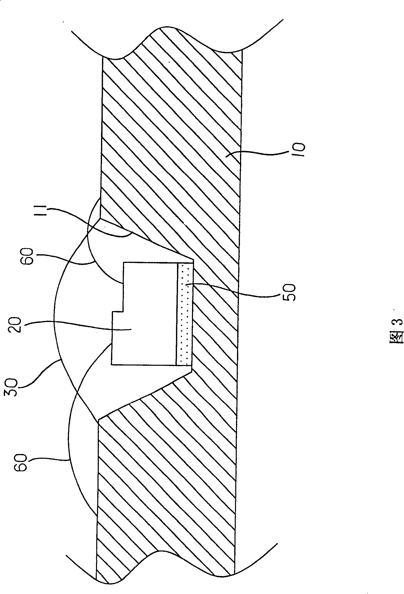
[0025] The structure of the multi-wavelength light-emitting diode and its light-emitting chip of the present invention aims to provide a light-emitting diode and its light-emitting chip structure that can produce correct light color and effectively improve the brightness performance effect, as shown in Figure 2, mainly in The bottom of the light-emitting chip 20 is provided with at least one fluorescent layer 50 with a predetermined wavelength. As shown in FIG. The gold wire 60 forms the circuit connection of the light-emitting chip 20, and under the coating of the encapsulation material 30, it forms a multi-wavelength light-emitting diode that allows the light source of the light-emitting chip 20 to combine with the wavelength of the fluorescent layer 50 to produce a desired light color. body.

[0026] S...


PUM


Abstract

The invention at least arranges a fixed-wavelength fluorescent layer at the bottom of a luminous wafer, can fix the luminous wafer on a carrier, uses metal wires to form circuit connection of the luminous wafer and composes a multi-wavelength luminous diode able to combine light source of the luminous wafer with wavelength of the fluorescent layer to produce desired light colors.

Description

technical field [0001] The present invention relates to light color display technology of light emitting diodes, and aims to provide a light emitting diode and its light emitting chip structure which can produce correct light color and effectively improve brightness performance. Background technique [0002] Press, the basic structure of a general light-emitting diode is to cover the light-emitting chip with related packaging materials, and use gold wires to form the connection between the electrodes of the light-emitting chip and related circuits, so that the light-emitting chip can produce a light source under the action of electrification of the light-emitting chip. , the light source is irradiated outward through the encapsulating material, and the light source for the light-emitting chip is further combined with the wavelength of the fluorescent material in the encapsulating material, so as to form the expected light color. [0003] As shown in FIG. 1 , it is a light-em...

Claims


Application Information

Patent Timeline
Patent Type & Authority Patents(China)
IPC IPC(8): H01L33/00H01L33/50
Inventor 李明顺孙平如何昌纬
Owner TAIWAN OASIS TECH CO LTD
Why Eureka
Try Eureka