Solenoid fuel jet valve

A fuel injection valve, electromagnetic technology, applied in the direction of fuel injection devices, charging systems, machines/engines, etc., can solve the problems of reduced commerciality, reduced connectivity between power supply couplers and power receiver couplers, etc., to achieve Effect of improving connectivity and merchandiseability

Active Publication Date: 2009-05-20
HITACHI ASTEMO LTD
View PDF8 Cites 0 Cited by
  • Summary
  • Abstract
  • Description
  • Claims
  • Application Information

AI Technical Summary

Problems solved by technology

[0006] However, when the power receiving coupler is formed by two-layer molding of such a synthetic resin, since the second resin molding layer shrinks due to cooling after molding, the outer end of the second resin molding layer and the first resin Gaps or protrusions are generated on the molding layer, which reduces the connectivity between the power supply coupler and the power reception coupler, resulting in a decrease in marketability

Method used


Image

  • Solenoid fuel jet valve
  • Solenoid fuel jet valve
  • Solenoid fuel jet valve

Examples


Embodiment 1

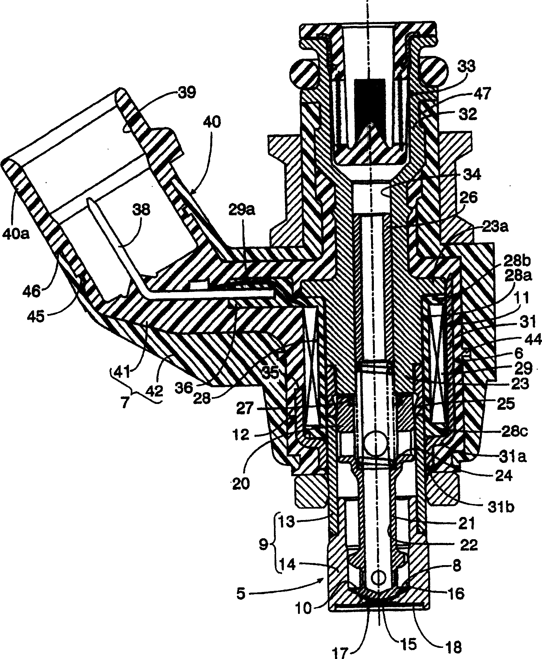
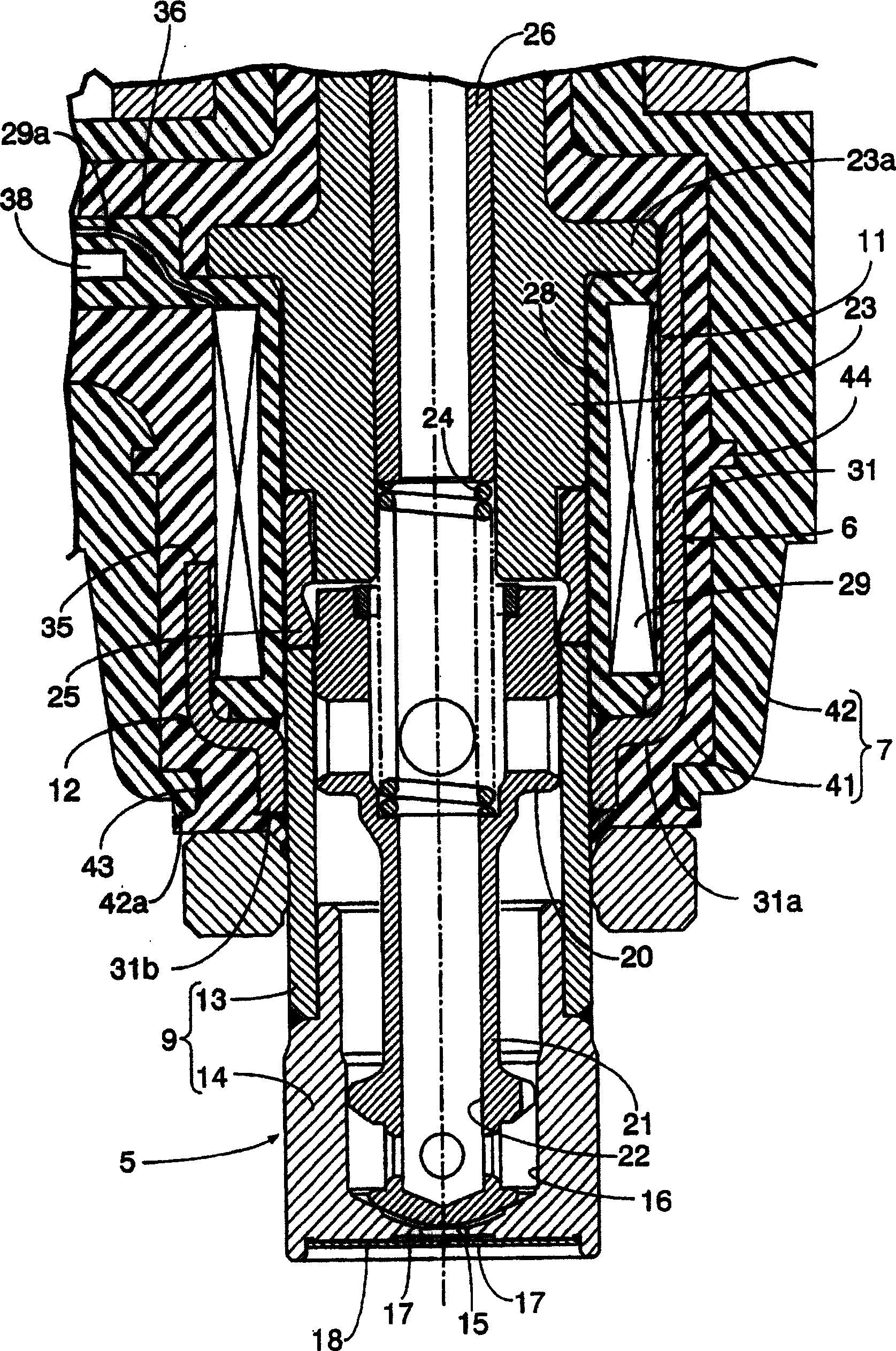
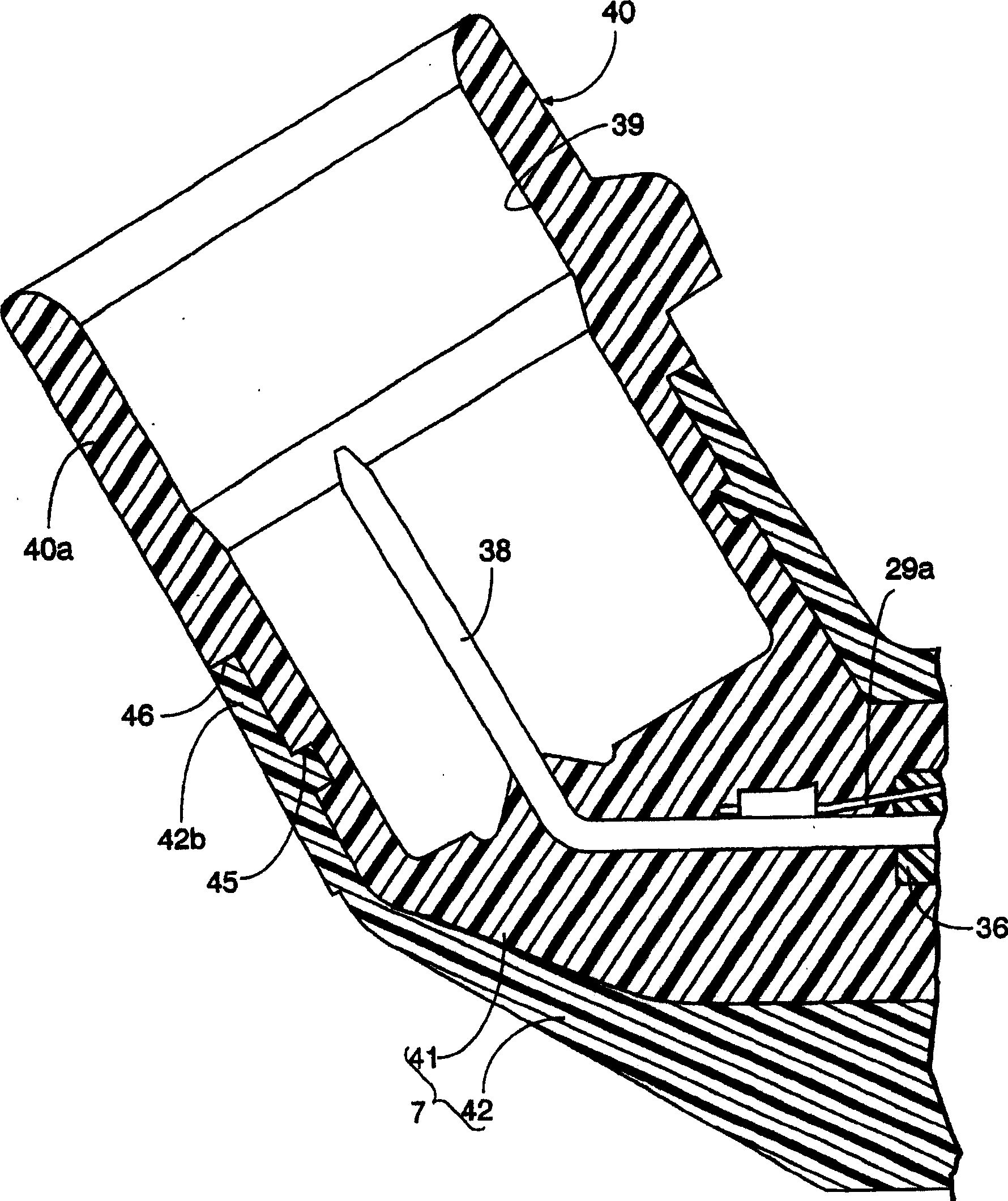
[0042] refer to Figure 1 ~ Figure 4 To describe the first embodiment of the present invention, first, in figure 1 Among them, an electromagnetic fuel injection valve for injecting fuel to an unillustrated engine has a valve operating part 5 that accommodates a valve body 10 in a valve casing 9 having a valve seat 8 at the front end, and the valve body 10 is seated on the The direction of the valve seat 8 is elastically biased; the solenoid part 6, wherein the coil assembly 11 that can generate the electromagnetic force that drives the valve body 10 to the side away from the valve seat 8, is housed in In the solenoid case 12 provided continuously with the valve case 9; the resin molded part 7 made of synthetic resin has a power receiving coupler 40 integrally, and covers at least the solenoid part 6, and the receiving The power coupler 40 faces the power receiving side connection terminal 38 connected to the coil 29 of the coil assembly 11 .

[0043] Also refer to figure 2...

Embodiment 2

[0068] Figure 5 Showing the second embodiment of the present invention, the engagement portion provided on the outer periphery of the first resin molded layer 41 along the axial direction of the valve case 5 at the portion corresponding to the coil assembly 11 may be an annular engagement recess 48, By restricting the displacement of the second resin molded layer 42 to the rear side by such engaging recessed portion 48, the same effect as that of the above-described first embodiment can be exhibited.

Embodiment 3

[0070] Image 6 Showing the third embodiment of the present invention, the engagement portion provided on the outer periphery of the first resin molded layer 41 along the axial direction of the valve case 5 at the portion corresponding to the coil assembly 11 may be an annular engagement facing forward. Even in the step portion 49 , by restricting the rearward displacement of the second resin molded layer 42 by the engaging step portion 49 , the same effects as those of the first and second embodiments described above can be exhibited.


PUM


Abstract

In an electromagnetic fuel injection valve in which a first resin-molded layer that is made of a synthetic resin, covers a solenoid section, and forms a coupler main portion that defines a framework of a power-receiving coupler is covered by a second resin-molded layer made of a synthetic resin that is different from that of the first resin-molded layer so that an outer face of the coupler main portion is exposed from a middle part up to the extremity of the coupler main portion, an endless engagement groove (45) is provided on the outer periphery of the middle part of the coupler main portion (40a) of the first resin-molded layer (41), the second resin-molded layer (42) engaging with the endless engagement groove (45), and an extending portion (42b) extending further outward than the engagement groove (45) is formed in the second resin-molded layer (42) so that the extending portion (42b) makes contact with an outer face of the coupler main portion (40a) when in a non-engaged state and covers the coupler main portion (40a). This prevents a gap or a bulge from occurring in a boundary section between the two resin-molded layers, thus improving the connectivity of a power-supplying coupler to a power-receiving coupler and the merchantability.

Description

technical field [0001] The present invention relates to an electromagnetic fuel injection valve comprising: a valve operating portion having a valve body accommodated in a valve case having a valve seat at the front end thereof, and the valve body being seated on the valve seat elastic force; the solenoid part, wherein the coil assembly that can generate the electromagnetic force that drives the valve body to the side away from the valve seat, is accommodated in the valve housing that is continuously arranged and extends backward. inside the solenoid case; and a resin molded part formed by covering a first resin molded layer made of synthetic resin with a second resin molded layer covering the solenoid part and forming a The main part of the coupler constituting the frame of the power receiving coupler facing the power receiving side connection terminal connected to the coil of the coil assembly, the second resin molded layer using the same as the first The resin molding laye...

Claims


Application Information

Patent Timeline
Patent Type & Authority Patents(China)
IPC IPC(8): F02M51/06F02M51/02
Inventor 赤羽根明田沼洋和
Owner HITACHI ASTEMO LTD
Why Eureka
Try Eureka