Check patentability & draft patents in minutes with Patsnap Eureka AI!

Scroll compressor

A scroll compressor and compressor technology, applied in the field of compressors, can solve the problems of general products without structure, leakage of working fluid, inconvenience, etc., and achieve the effects of reducing costs, reducing material costs, and preventing performance degradation.

Inactive Publication Date: 2009-06-03
LG ELECTRONICS (TIANJIN) APPLIANCES CO LTD
View PDF6 Cites 0 Cited by
  • Summary
  • Abstract
  • Description
  • Claims
  • Application Information

AI Technical Summary

Problems solved by technology

[0017] Accordingly, even if there is a gasket 13 between the high and low pressure separation plate 11 and the fixed scroll 8, the working fluid with the high pressure portion S2 will leak because one side of the high and low pressure separation plate 11 is misaligned with the fixed scroll 8 to the disadvantages in between
[0018] This shows that above-mentioned existing scroll compressor obviously still has inconvenience and defect in structure and use, and urgently needs to be further improved
In order to solve the problems existing in scroll compressors, relevant manufacturers have tried their best to find a solution, but no suitable design has been developed for a long time, and general products have no suitable structure to solve the above problems. Obviously, it is a problem that relevant industry players are eager to solve.

Method used


Image

  • Scroll compressor
  • Scroll compressor
  • Scroll compressor

Examples


Embodiment Construction

[0053] In order to further explain the technical means and effects of the present invention to achieve the intended purpose of the invention, the following describes the specific implementation, structure, features and effects of the scroll compressor proposed in accordance with the present invention with reference to the accompanying drawings and preferred embodiments. , The detailed description is as follows.

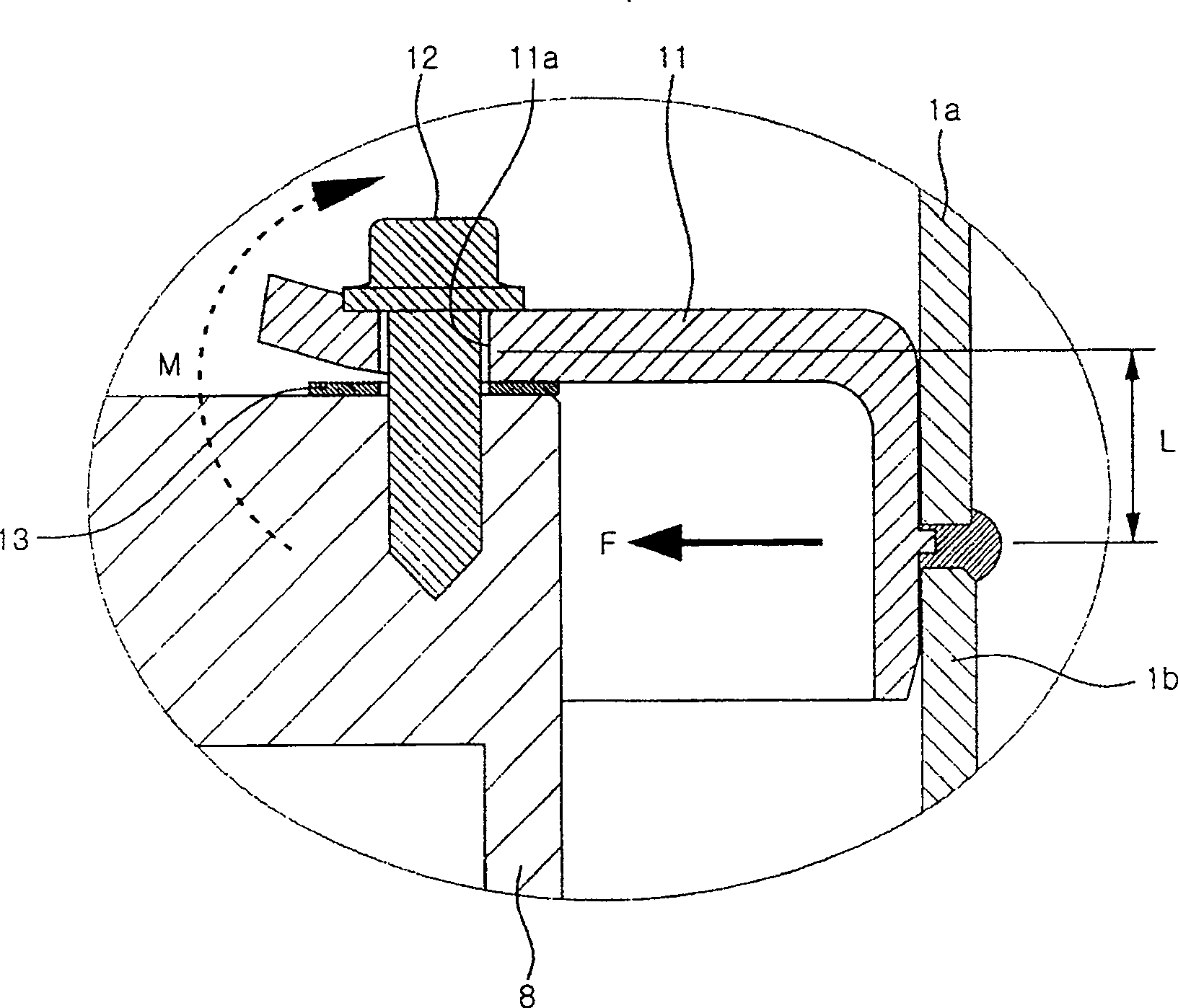
[0054] See Figure 3 to Figure 6 Shown. image 3 It is a longitudinal sectional view of the structure of a valuable embodiment of the scroll compressor of the present invention, Figure 4 Yes image 3 An enlarged schematic diagram of the part of the inside of the ellipse, Figure 5 Is a schematic diagram of the high and low pressure separation plate of the embodiment of the present invention, Figure 6 It is a schematic diagram of the splash prevention plate of the embodiment of the present invention.

[0055] As shown in the above figure, the case 20 is composed of an upp...


PUM


Abstract

The scroll compressor consists of a casing to form a sealed space; a compressor unit comprising a rotating scroll and a fixed scroll; a power generating part installed inside the casing to provide scroll rotating power; and a high pressure and lower pressure separating plate to separate the space inside the casing into a low pressure part and a high pressure part separating for the fluid before and after compression and with one side fixed onto the fixed scroll and the other side fixed onto the inside wall of the casing. The said fixed scroll is superposed and area contacted to the separating plate and thus can prevent the performance degradation caused by overstocked compressed work fluid.

Description

Technical field [0001] The invention relates to a compressor, in particular to a scroll compressor having an involute tooth profile and compressing a working fluid by rotating two scrolls that coincide with each other. Background technique [0002] See figure 1 with figure 2 Shown. figure 1 Is a longitudinal section view of a scroll compressor of the prior art, figure 2 Yes figure 1 An enlarged schematic diagram of the part of the inside of the ellipse. [0003] As shown in the figure, the chassis is composed of an upper end cover 1a, a housing 1b, and a lower end cover 1c. One side of such a case 1 has a suction pipe SP for sucking in working fluid from outside and a discharge pipe DP for discharging working fluid. At this time, the working fluid sucked into the suction pipe SP is compressed by the relatively low-pressure low-pressure part S1, moves to the high-pressure part S2, and flows out through the discharge pipe DP. [0004] The upper frame 2 is fixed to the inside o...

Claims


Application Information

Patent Timeline
IPC IPC(8): F04C18/02
Inventor 南泰熙陈弘均朱伦秀
Owner LG ELECTRONICS (TIANJIN) APPLIANCES CO LTD
Features
  • R&D
  • Intellectual Property
  • Life Sciences
  • Materials
  • Tech Scout
  • Unparalleled Data Quality
  • Higher Quality Content
  • 60% Fewer Hallucinations
Learn More