Switch device of parallel connection vacuum arc extinguishing chamber

A vacuum interrupter and switchgear technology, which is applied to electric switches, high-voltage/high-current switches, high-voltage air circuit breakers, etc., can solve the problems of complex structure, cost increase, space limitation, etc. High contact reliability ensures normal operation

Inactive Publication Date: 2009-06-03
NINGBO TIANAN GRP CO LTD
View PDF5 Cites 0 Cited by
  • Summary
  • Abstract
  • Description
  • Claims
  • Application Information

AI Technical Summary

Problems solved by technology

[0002] As a vacuum load switch for breaking the load current and closing the short-circuit current, there are currently two structures. One is the series installation of the isolation knife switch and the vacuum interrupter. When in use, the isolation knife switch and the vacuum interrupter must bear The dynamic and thermal stable current and working current, and the mechanical transmission structure is more complicated and the cost is higher. The typical models are FZN25, FN16, etc.; the other is the parallel installation of the isolation switch and the vacuum interrupter, and only the isolation switch can bear The dynamic and thermal stable current and working current, while the vacuum interrupter only plays the role of arc extinguishing when breaking the load current, that is, the isolation knife switch is the main circuit, and the vacuum interrupter is the auxiliary arc extinguishing circuit. This structure is simple, lower cost
Parallel structure At present, the typical design in China is to add a vacuum interrupter to the static main contact of the ordinary rotary blade type isolating switch. Therefore, the switch is generally used in outdoor places. The common models are: FZW20, FZW16, FZW32, FZW58, etc. If it is used in an indoor switch cabinet, not only the space is limited, but also the busbar room on the upper part of the switch cabinet and the lower part of the switch cabinet cannot be used. The load switch chamber or cable chamber naturally forms an independent compartment. Therefore, the general indoor vacuum load switch is designed as a series structure, which makes the structure complicated and the cost increased. The electrical contact of the blade-type moving main contact is not reliable and affects normal operation of the circuit

Method used


Image

  • Switch device of parallel connection vacuum arc extinguishing chamber
  • Switch device of parallel connection vacuum arc extinguishing chamber
  • Switch device of parallel connection vacuum arc extinguishing chamber

Examples


Embodiment Construction

[0018] The embodiments of the present invention will be described in further detail below in conjunction with the accompanying drawings.

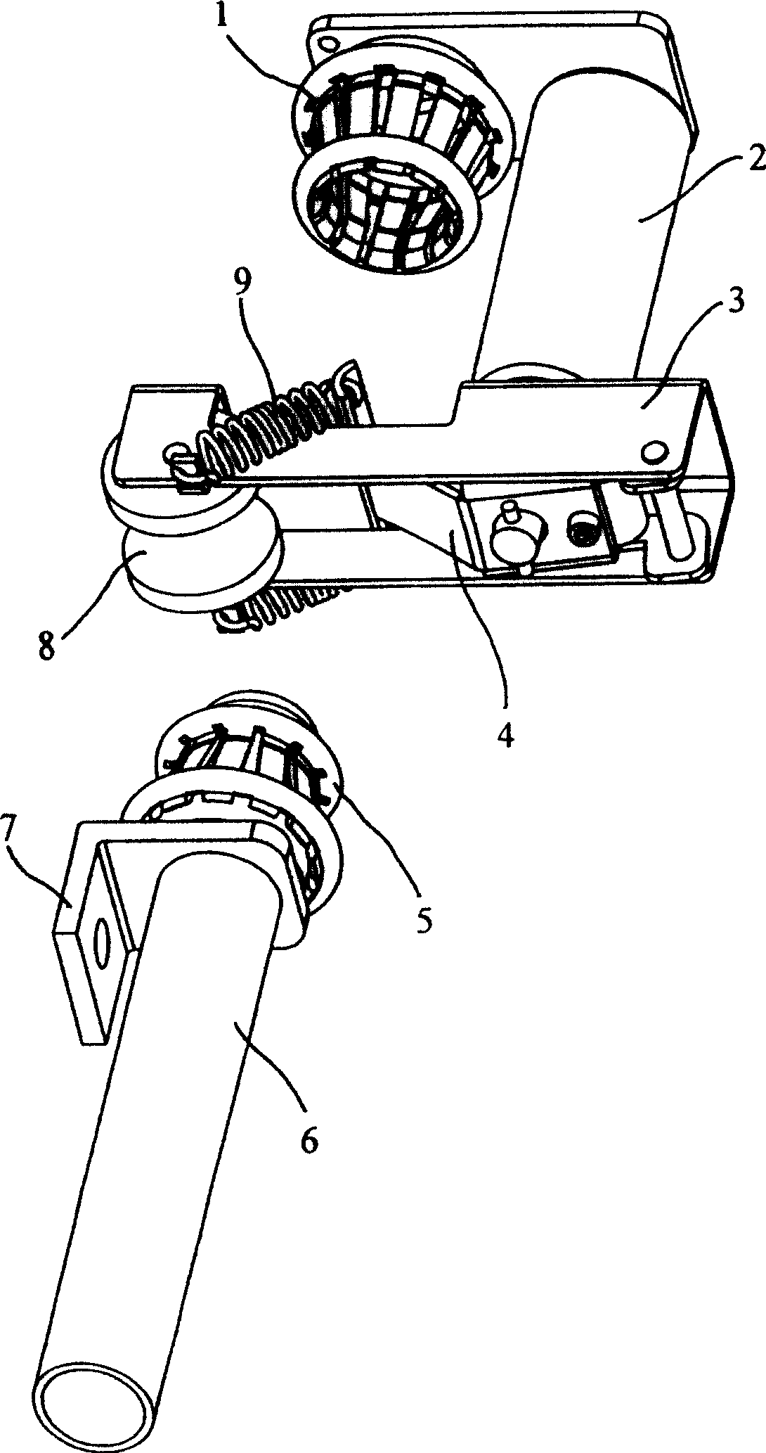
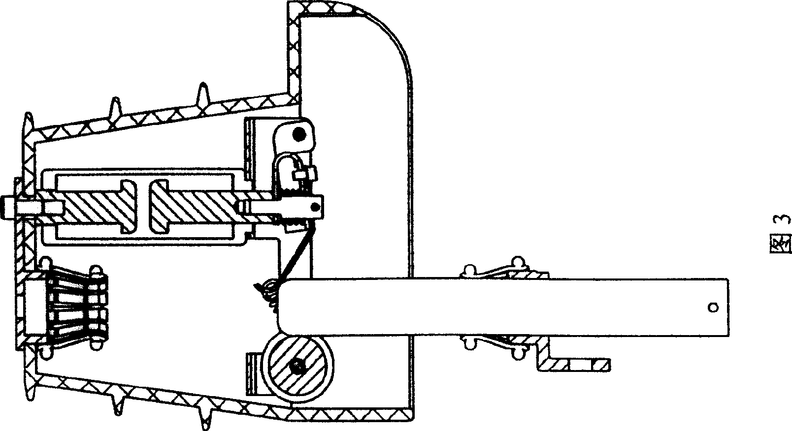
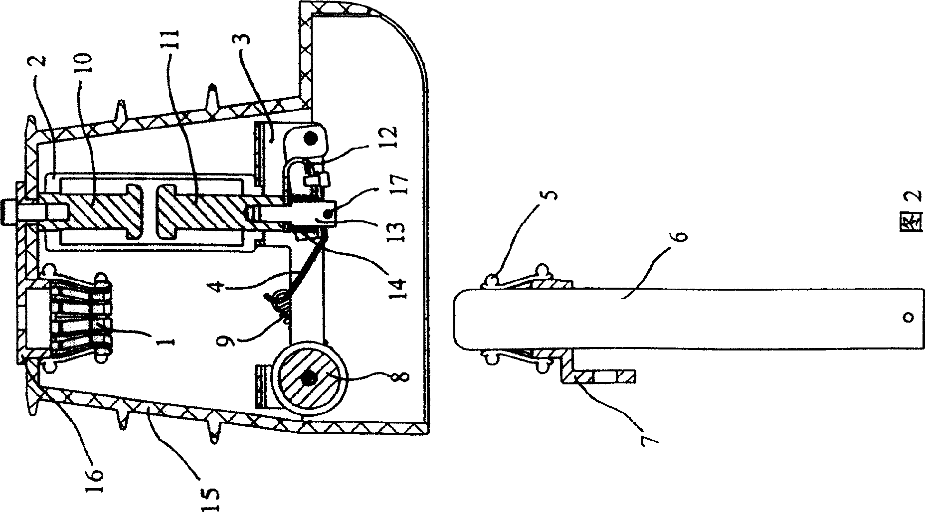
[0019] Such as figure 1 As shown in ~2, the switchgear of the parallel vacuum interrupter includes an insulating cover 15 and a bracket 3 fixed on the insulating cover, and a main circuit and an auxiliary circuit are installed in parallel in the insulating cover.

[0020] The upper conductive seat 16 at the static end of the main circuit is fixed on the top of the insulating cover together with the plum blossom-shaped static main contact 1, and the circular tube-shaped moving main contact 6 at the moving end is interspersed with the mutually fixed plum blossom-shaped transition contact seat 5 and the lower conductive In the seat 7, the lower conductive seat is a conductor fixed on the insulator of the load switch. The moving main contact is driven by the insulating arm (not shown in the figure) to move up and down in a straight line track, ...


PUM


Abstract

The disclosed switch paralleled with a vacuum arc-extinguishing room comprises: a fixed and circular-tube movable contact vertical arranged in an insulation cover as the main loop, and a vacuum arc-extinguishing room as the auxiliary loop, wherein using both an arc striking Z-arm connected with a separation brake spring and an over-travel spring to drive the contacts and form assist loop electric connection. This invention has high contact and running reliability, and reduces size and cost.

Description

technical field [0001] The invention relates to a vacuum load switch, in particular to a switch device for parallel vacuum interrupters. Background technique [0002] As a vacuum load switch for breaking the load current and closing the short-circuit current, there are currently two structures. One is the series installation of the isolation knife switch and the vacuum interrupter. When in use, the isolation knife switch and the vacuum interrupter must bear The dynamic and thermal stable current and working current, and the mechanical transmission structure is more complicated and the cost is higher. The typical models are FZN25, FN16, etc.; the other is the parallel installation of the isolation switch and the vacuum interrupter, and only the isolation switch can bear The dynamic and thermal stable current and working current, while the vacuum interrupter only plays the role of arc extinguishing when breaking the load current, that is, the isolation knife switch is the main...

Claims


Application Information

Patent Timeline
Patent Type & Authority Patents(China)
IPC IPC(8): H01H33/664
Inventor 朱佩龙
Owner NINGBO TIANAN GRP CO LTD
Why Eureka
Try Eureka