Al technical title is built by PatSnap Al team. It summarizes the technical point description of the patent document.
A transmission device and wing rudder technology, which is applied in the direction of rudder steering and steering, can solve the problems of ship control performance limitations, achieve the effects of improving seaworthiness, reducing energy consumption, and improving the hydrodynamic performance of the rudder
Inactive Publication Date: 2009-06-10
HARBIN ENG UNIV
View PDF8 Cites 0 Cited by
Summary
Abstract
Description
Claims
Application Information
AI Technical Summary
This helps you quickly interpret patents by identifying the three key elements:
Problems solved by technology
Method used
Benefits of technology
Problems solved by technology
The common feature of these transmissions is that there is a fixed ratio of rotation angle between the main rudder and the wing rudder, that is, the rotation angle of the wing rudder is in a fixed ratio to the rotation angle of the main rudder, and the wing rudder cannot rotate freely without being restricted by the main rudder.
Compared with the common symmetrical section rudder, the rudder / wing rudder with fixed rotation angle ratio improves the power control performance, but due to the fixed rotation angle ratio, the wing rudder cannot rotate freely from the main rudder, which limits the improvement of ship control performance
Method used
Image
Click on the blue label to locate the original text in one second.
Reading with bidirectional positioning of images and text.
Examples
Embodiment Construction
[0021] The present invention is described in more detail below in conjunction with accompanying drawing example:
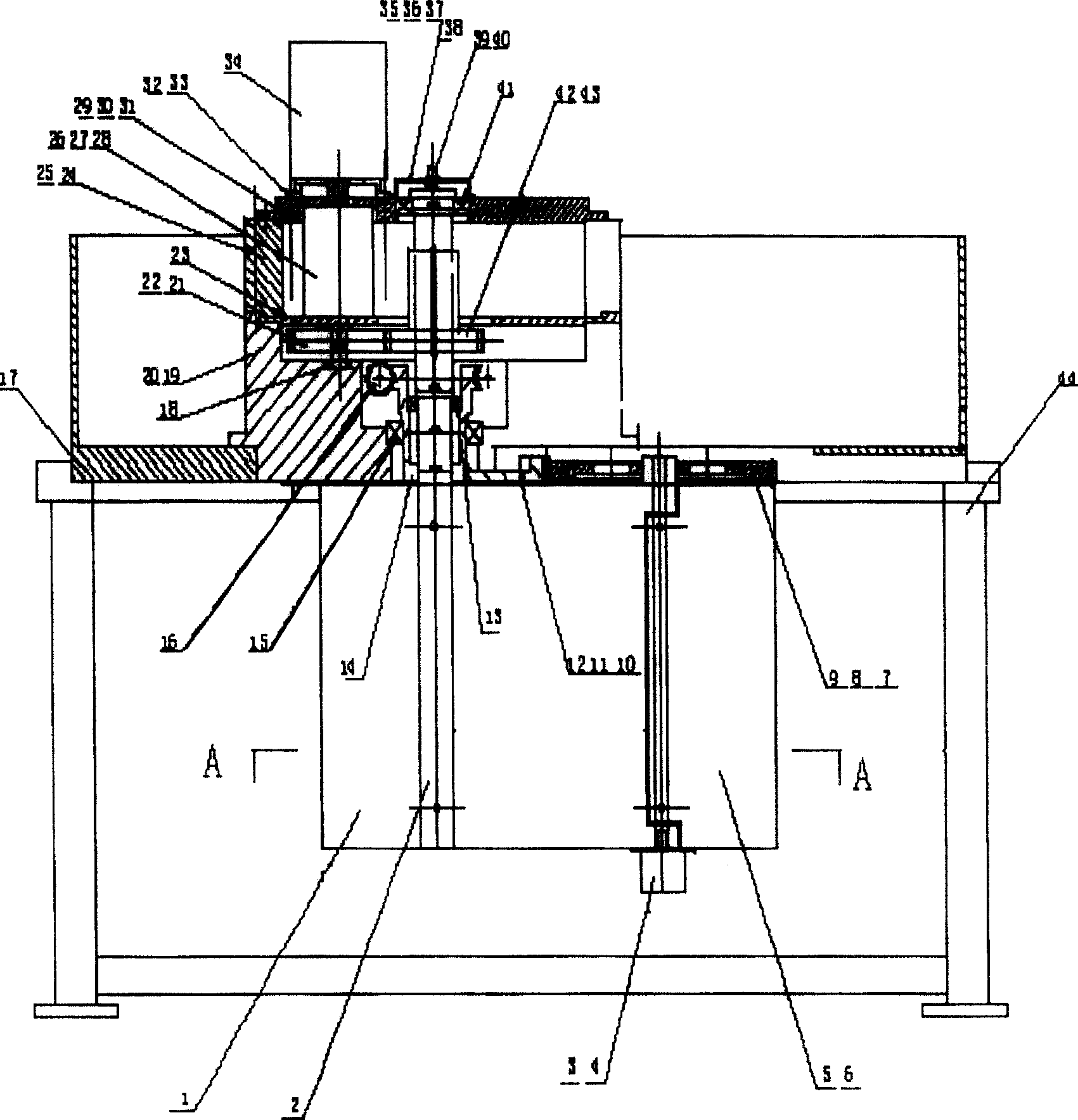
[0022] combine figure 1 with figure 2 , the composition of the ship rudder / wing rudder arbitrary rotation angle ratio transmission device includes: main rudder blade 1, main rudder shaft 2, photoelectric code disc 3, screw 4, wing rudder blade 5, pin 6, wing rudder shaft 7, wing rudder slave Driven gear 8, flat key 9, wing rudder driven gear 10, pin 11, screw 12, inner bearing 13, worm gear sleeve shaft 14, outer bearing 15, worm motor assembly 16, outer base 17, gear bearing 18, base 19 , Mounting screw 20, main shaft driving gear 21, transmission key 22, intermediate support plate 23, upper base 24, connecting bolt 25, harmonic reducer 26, fixing bolt 27, input bushing 28, upper cover 29, fixing bolt 30 , flat key 31, top motor support cover 32, screw 33, spindle motor 34, top code disc support cover 35, screw 36, code disc coupling 37, fastening screw 38, ph...
PUM
Abstract
The invention provides a boat helm / wing rudder discretional rotation angle transmission device. The invention consists of a main rudder blade, a main rudderpost, a photo-electricity encoder, a wing rudder leaf, a wing rudder shaft, a wing rudder driven gear, an internal bearing, a turbine sleeve shaft, an external bearing, a worm motor component, an external base seat, a gear bearing, a bottom seat, a main shaft drive gear, a middle supporting plate, an upper base seat, a harmonic reducer, an input shaft sleeve, an upper cover, a top motor supporting cover, a main shaft motor, a top encoder supporting cover, an encoder coupler, a photo-electricity encoder, a main shaft driven gear, a frame, etc. The invention enables the rotation of the wing rudder out of the restriction of the main rudder, namely, a small control surface which correspondingly and independently motions is added on the rudder to obviously improve the fluid power performance of the rudder, thus improving the course control performance of the rudder system. The invention has the advantages of reducing the energy consumption, improving the reliability and improving the navigability of the boat.
Description
(1) Technical field [0001] The invention relates to a propulsion device or a steering device of a ship. Specifically, it is a transmission device for joint control of ship rudder / wing rudder. (2) Background technology [0002] Two wings with the same aspect ratio and the same chord length, under the same angle of attack, the curved wing with camber has a larger lift coefficient than the wing with symmetrical section, because the effect of camber is equivalent to increasing Bigger angle of attack. The rudder / wing rudder is to divide the rudder into two parts, the main rudder and the wing rudder according to a certain ratio. Through the transmission device, an angle is formed between the main rudder and the wing rudder. In fact, it is to change a general streamlined rudder into a certain Cambered rudder. In a broad sense, wing rudders are equivalent to variable camber wings, which can provide greater lift at the same main rudder angle before the incoming flow separates, gre...
Claims
Application Information
Patent Timeline
Application Date:The date an application was filed.
Publication Date:The date a patent or application was officially published.
First Publication Date:The earliest publication date of a patent with the same application number.
Issue Date:Publication date of the patent grant document.
PCT Entry Date:The Entry date of PCT National Phase.
Estimated Expiry Date:The statutory expiry date of a patent right according to the Patent Law, and it is the longest term of protection that the patent right can achieve without the termination of the patent right due to other reasons(Term extension factor has been taken into account ).
Invalid Date:Actual expiry date is based on effective date or publication date of legal transaction data of invalid patent.