Check patentability & draft patents in minutes with Patsnap Eureka AI!

Magnetoresistive sensor and Magnetoresistive head

A magnetoresistance and sensor technology, applied in the fields of magnetic field controlled resistors, manufacturing flux-sensitive magnetic heads, magnetic recording heads, etc., can solve problems such as increasing the reading gap

Inactive Publication Date: 2009-06-17
HITACHI GLOBAL STORAGE TECH NETHERLANDS BV
View PDF7 Cites 0 Cited by
  • Summary
  • Abstract
  • Description
  • Claims
  • Application Information

AI Technical Summary

Problems solved by technology

Thus both the terminal and the insulating layer increase the size of the read gap

Method used


Image

  • Magnetoresistive sensor and Magnetoresistive head
  • Magnetoresistive sensor and Magnetoresistive head
  • Magnetoresistive sensor and Magnetoresistive head

Examples


Embodiment Construction

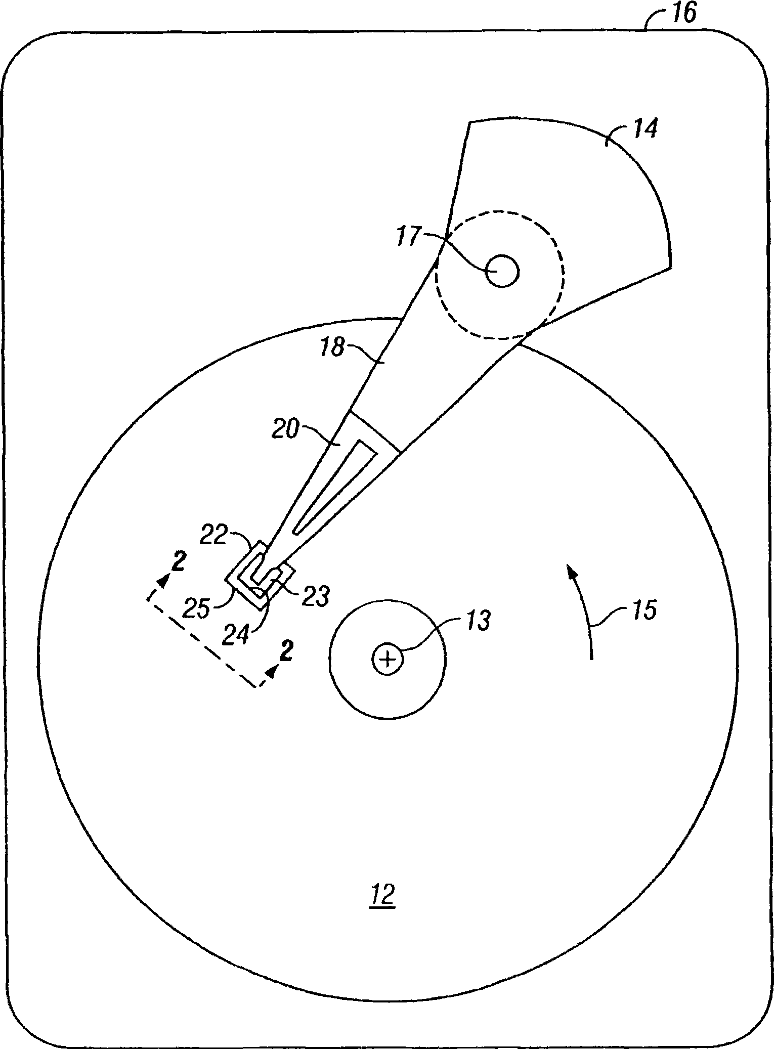
[0016] The sensor of the present invention can be used as a magnetoresistive (MR) read head for a magnetic recording disk drive, so reference will be made to Figure 1-3 Briefly describe the operation of a conventional disk drive. However, the sensor of the present invention is fully applicable as a magnetic field sensor and as a read head for magnetic recording media other than magnetic recording disks.

[0017] figure 1 is a block diagram of a conventional magnetic recording hard drive. The disk drive includes a magnetic recording disk 12 and a rotating voice coil motor (VCM) actuator 14 supported on a disk drive housing or base 16 . Disk 12 has a center of rotation 13 and is rotated in direction 15 by a spindle motor (not shown) mounted to base 16 . The actuator 14 rotates about an axis 17 and includes a rigid actuator arm 18 . A generally flexible cantilever 20 includes a flexure element 23 and is connected to the end of the arm 18 . A head mount or air-bearing slider...


PUM


Abstract

Magnetoresistive sensors and magnetoresistive read heads. The present invention relates to a spin accumulation effect based disc drive magnetoresistive (MR) read head without electrical terminals and associated insulating layers in the read gap. A spin accumulation type MR read head has a conductive strip on an insulating layer on the lower magnetic shield, the strip has a first end facing the disk at the detection end of the head and is recessed from said detection end at the rear end of the head the second end of . At the detection end of the head, the upper magnetic shield is on the free layer without the insulating layer. A resistance detection circuit is electrically coupled to the upper shield and the lower shield at the rear end of the header. At the rear end of the head, electrical terminals are located on the fixed ferromagnetic layer and are electrically insulated from the upper shield. At the rear end of the header, a current supply circuit is electrically coupled to the terminals and the lower shield.

Description

technical field [0001] The present invention relates generally to magnetoresistive (MR) sensors, such as MR read heads for magnetic recording disk drives, and more particularly to MR sensors based on the spin accumulation effect. Background technique [0002] A class of conventional MR sensors, often referred to as "spin valve" (SV) sensors, has a stack of layers comprising two ferromagnetic layers separated by a nonmagnetic spacer layer. One ferromagnetic layer has its magnetization direction pinned, for example by exchange coupling with an adjacent antiferromagnetic layer, and the other ferromagnetic layer has its magnetization direction "free" to rotate in the presence of an external magnetic field. The rotation of the magnetization of the free layer relative to the magnetization of the pinned layer can be detected as a change in resistance using a sense current applied to the sensor. The SV MR read head used in all current magnetic recording hard drives operates with a ...

Claims


Application Information

Patent Timeline
Patent Type & Authority Patents(China)
IPC IPC(8): H01L43/08G11B5/39G01R33/09
CPCG01R33/093G11B5/3903G11B5/398G11B5/3909
Inventor 马修·J·卡里布鲁斯·A·格尼
Owner HITACHI GLOBAL STORAGE TECH NETHERLANDS BV
Features
  • R&D
  • Intellectual Property
  • Life Sciences
  • Materials
  • Tech Scout
  • Unparalleled Data Quality
  • Higher Quality Content
  • 60% Fewer Hallucinations
Learn More