Surface mountable transceiver

a transceiver and surface mount technology, applied in the direction of fixed connections, coupling device connections, instruments, etc., can solve the problems of system not operating at its maximum potential, use of known transceivers, and inacceptable use of receptacles mounted to printed circuit boards

Inactive Publication Date: 2002-03-19
STRATOS INT
View PDF5 Cites 56 Cited by
  • Summary
  • Abstract
  • Description
  • Claims
  • Application Information

AI Technical Summary

Problems solved by technology

In order to save space, the use of a receptacle mounted to a printed circuit board is not acceptable and in other situations a printed circuit board does not utilize through holes into which pins may be projected and secured to the printed circuit board.
Additionally, another problem is present with the use of known transceivers.
If the impedances are not matched, the system does not operate at its maximum potential since the flow of energy flowing from the transceiver to the host device and from the host device to the transceiver is restricted.
The total cost of the additional electronic components required for the impedance matching includes the purchase cost of the additional electronic components, the storage cost of keeping the additional electronic components in inventory, and the labor cost of installing the additional electronic components.
Furthermore, the additional electronic components occupy space, thus increasing the size of the host device, which is not desirable.

Method used


Image

  • Surface mountable transceiver
  • Surface mountable transceiver
  • Surface mountable transceiver

Examples


Embodiment Construction

Referring now to the drawings, wherein like reference numerals designate identical or corresponding parts throughout the several views, and more particularly to FIGS. 1-6 thereof, an embodiment of the present invention is a device or transceiver 10 which is displayed therein.

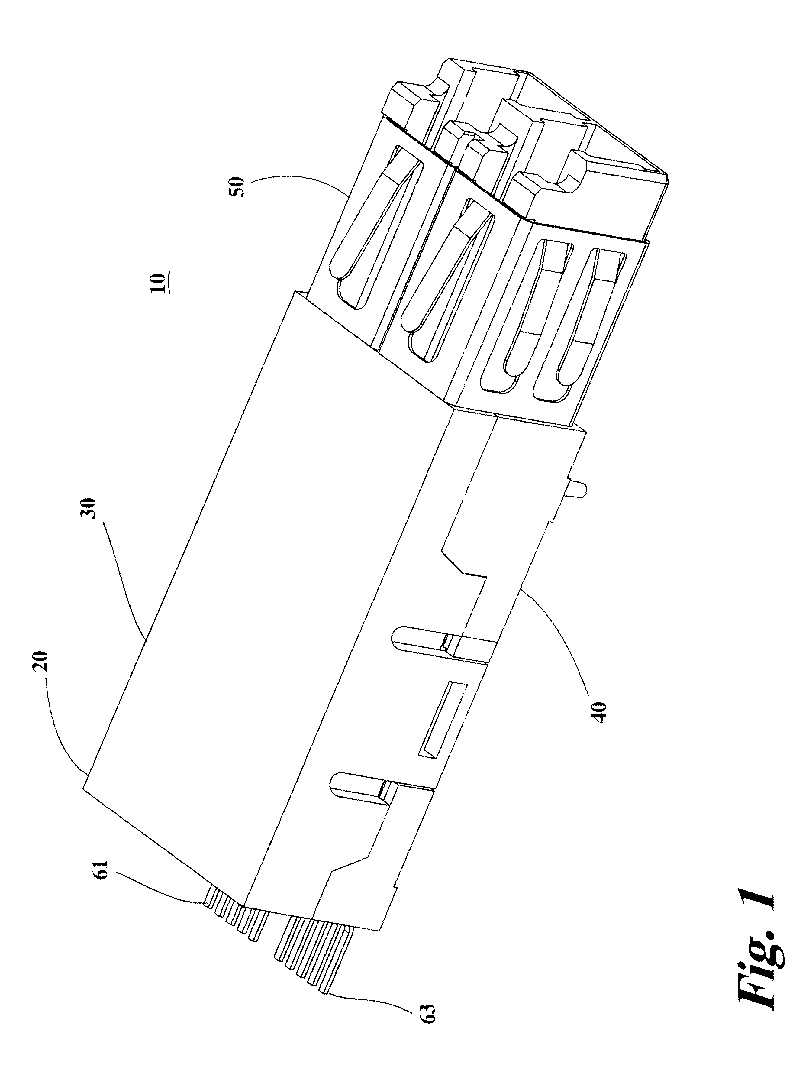
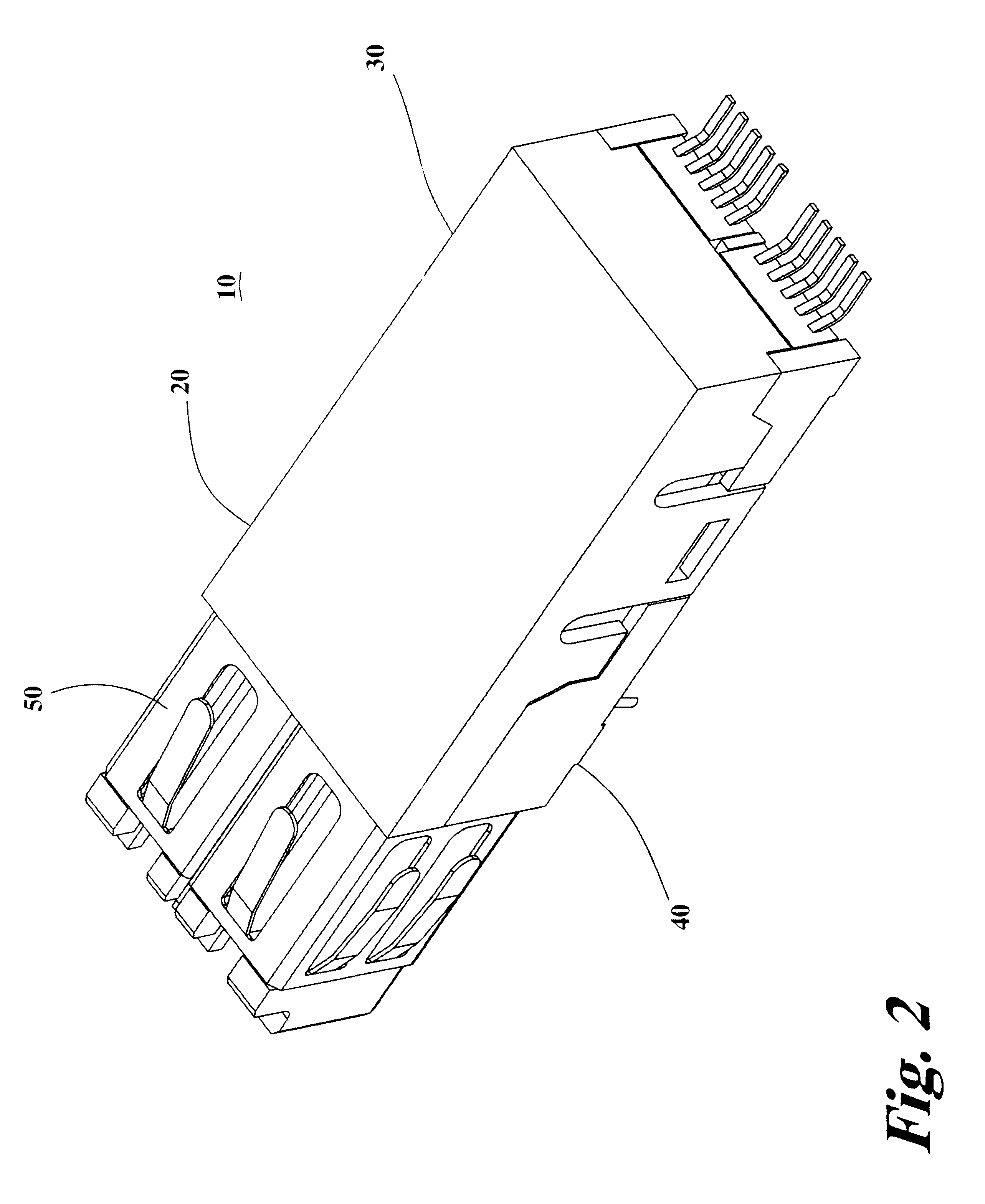
FIG. 1 is a perspective view of the transceiver 10. FIG. 2 is a perspective view of the transceiver 10 taken from an angle different than the angle presented in FIG. 1. FIGS. 1 and 2 show the housing 20, the electro-magnetic shield 50, the first electrical connector 61, and the second electrical connector 63.

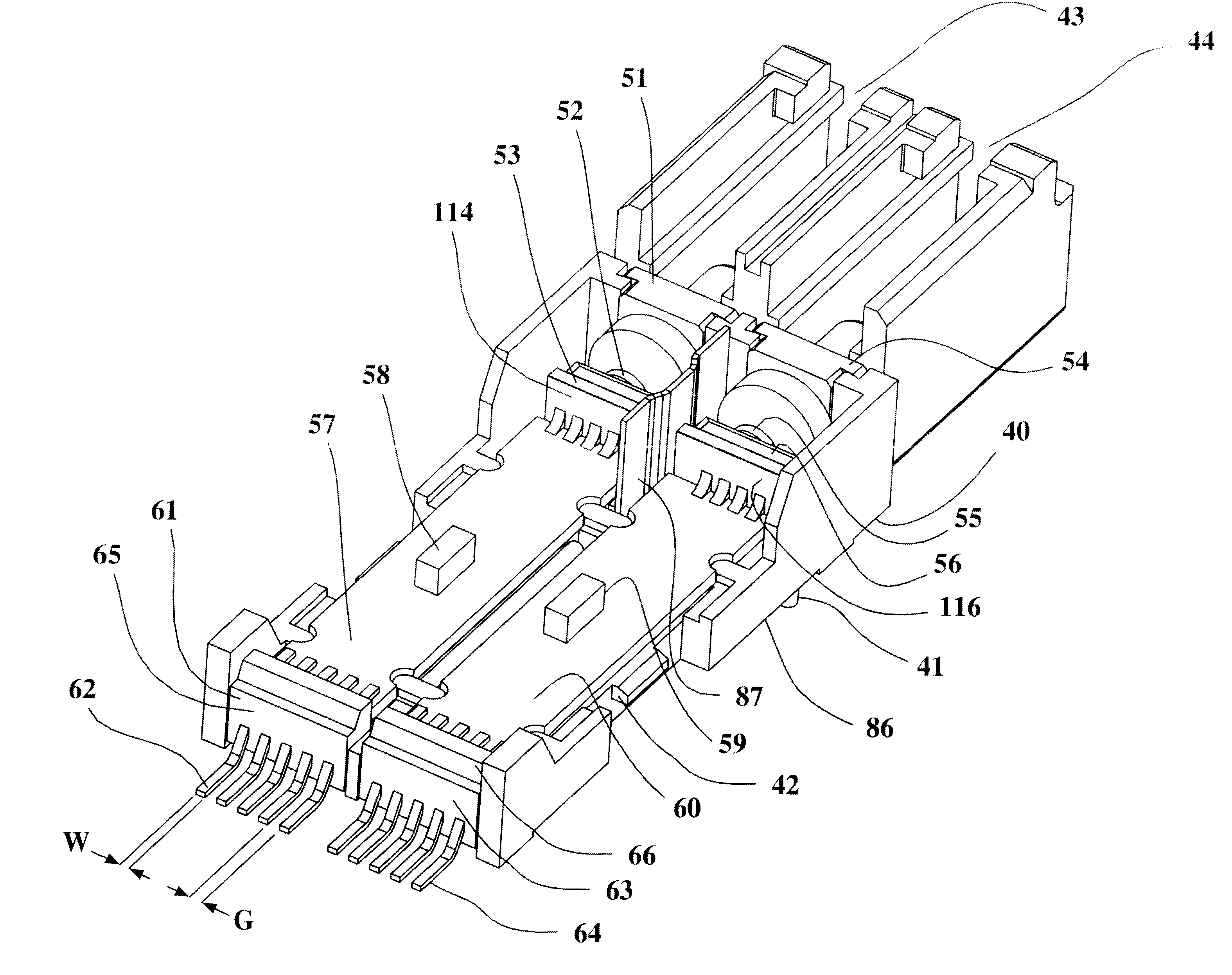
FIG. 3 is a perspective view of the transceiver 10 having the cover 30 and the electromagnetic shield 50 removed thus exposing the base 40 and the components mounted within the base 40 of the housing 20. FIG. 4 is a perspective view of the base 40 of the housing 20 of the transceiver 10 taken from an angle different than the angle presented in FIG. 3. The base 40 of the housing 20 includes a first fiber opti...


PUM


Abstract

The transceiver includes a housing, a transmitting optical sub-assembly mounted in the housing, a receiving optical sub-assembly mounted in the housing, a first electrical connector associated with the transmitting optical sub-assembly, a second electrical connector associated with the receiving optical sub-assembly, and an electro-magnetic shield mounted on the housing. The housing includes a first fiber optic connector receptacle, a second fiber optic connector receptacle, and a first side, and the housing is made of an electrically conductive material.

Description

1. Field of the InventionThe present invention pertains to a transceiver. The invention more particularly concerns a transceiver that is mountable to a surface of a printed circuit board.2. Discussion of the BackgroundA transceiver is a device that contains at least one opto-electronic receiver and at least one opto-electronic transmitter. An opto-electronic transmitter receives electrical signals, converts them to light signals, and then transmits the light signals. An opto-electronic receiver receives light signals, converts them to electrical signals, and then transmits the electrical signals. Known transceivers are soldered to printed circuit boards where their pins and posts extend through through holes formed in the printed circuit board or the transceivers are plugged into receptacles which are in turn mounted to a printed circuit board.In order to save space, the use of a receptacle mounted to a printed circuit board is not acceptable and in other situations a printed circui...

Claims


Application Information

Patent Timeline
Patent Type & Authority Patents(United States)
IPC IPC(8): H01R12/16H01R12/00G02B6/42H01R12/50
CPCH01R23/6873G02B6/4277G02B6/4246G02B6/4292H01R13/6594
Inventor GILLILAND, PATRICK B.DWARKIN, ROBERT M.JINES, CARLOSMEDINA, RAUL
Owner STRATOS INT
Why Eureka
Try Eureka