Magnetic head for perpendicular recording

a magnetic disk drive and perpendicular technology, applied in the direction of magnetic recording heads, data recording, instruments, etc., can solve the problems of deteriorating device life, affecting the recording quality, so as to reduce the protrusion and reduce the leakage of magnetic fields

Inactive Publication Date: 2006-04-27
WESTERN DIGITAL TECH INC
View PDF15 Cites 56 Cited by
  • Summary
  • Abstract
  • Description
  • Claims
  • Application Information

AI Technical Summary

Benefits of technology

[0021] According to the present invention, it is possible to provide a perpendicular recording magnetic head capable of reducing leakage magnetic fields from the soft magnetic films on the air bearing surface side and reducing the protrusion of the soft magnetic films in the direction of the air bearing surface side due to thermal deformation of the soft magnetic films.

Problems solved by technology

Accordingly, the problem occurs in that when the element is activated in a high-temperature condition, the shield section of a large volume is thermally expanded to cause the end of the soft magnetic film to protrude from the air bearing surface and come into contact with the recording medium surface.
In addition, even in the state where such contact can be avoided, local distortion effects on the air bearing surface appear as the tribological problem in that the lubricating material previously applied to the medium surface leaps onto the corresponding section.
Hence, the deterioration of device life and other problems occur.
The increase in the magnetic distance between the element and the recording medium may cause the effect that during recording, applying a strong magnetic field to the recording medium becomes difficult and this makes magnetic information writing at high density virtually impossible.
Furthermore, because of the construction where the coil is to be covered with a large shield, the problem is also observed in that spatially passing magnetic fluxes originally not involved with recording are collected by the shield and guided to the recording medium.
Hence, the need arises to limit the quantity of fluxes which the coil can generate, and this results in the problem in that a strong magnetic field cannot be generated.
As can be seen from these facts, the performance of the device is not improved to a level at which it can bring out the advantages of high density that the perpendicular magnetic recording scheme possesses.
Accordingly, magnetic coupling between the soft magnetic film provided in the vicinity of the air bearing surface and the soft magnetic film coupled to the main magnetic pole piece is very weak and thus a reduction effect against the leakage magnetic fields is extremely insignificant.
This means that since the ends of the soft magnetic films covering the coil from top and bottom face the air bearing surface and are not in an approaching state with respect thereto, an overflow of fluxes into the main magnetic pole piece results in excess fluxes leaking from the vicinity of the front end which determines track width.

Method used


Image

  • Magnetic head for perpendicular recording
  • Magnetic head for perpendicular recording
  • Magnetic head for perpendicular recording

Examples


first embodiment

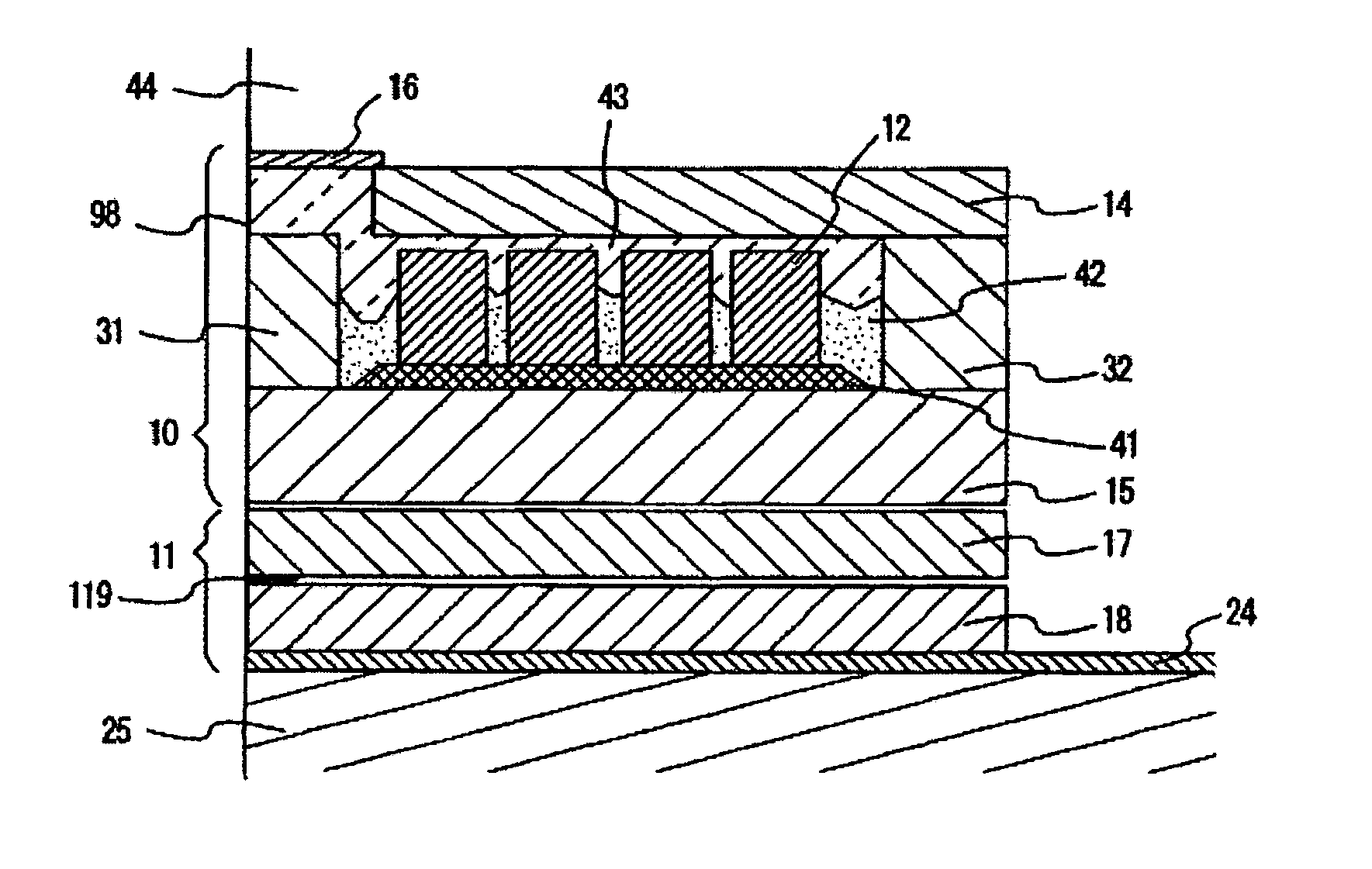
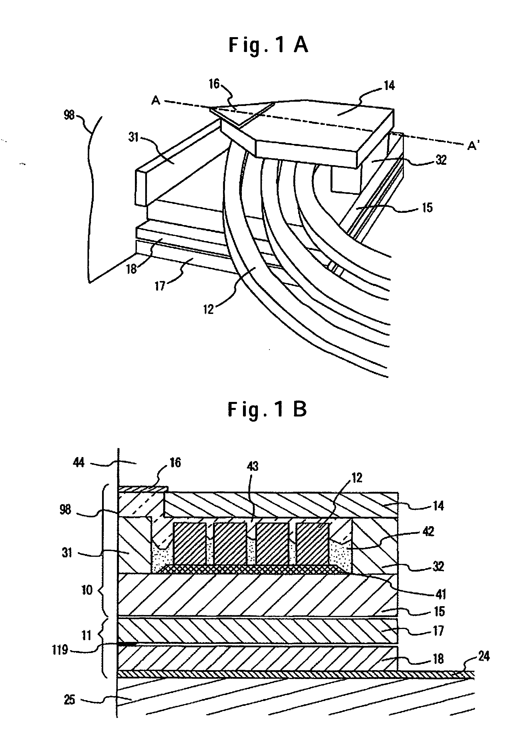
[0047] A perpendicular recording magnetic head according to the present invention is described below using FIGS. 1A and 1B. FIG. 1A is a view taken from an oblique direction of a magnetic head element section. FIG. 1B is a cross-sectional view taken along line A-A′ of FIG. 1A. A write functional section includes a coil conductor 12, a second soft magnetic film (second soft magnetic film pattern) 14 and a first soft magnetic film (first soft magnetic film pattern) 15, these soft magnetic films being provided in such a form as to cover the coil conductor from top and bottom and being magnetically connected to each other, and a main magnetic pole piece 16 defining a recording track width. These structural members are formed after formation of a substrate 25 (slider) made of Al2O3—TiC, an underlayer 24 laminated thereon with Al2O3, and a read functional section 11 produced further thereon for information reading. The read functional section 11 is constructed so as to have a reading elem...

second embodiment

[0073] In the above-described second embodiment with the pedestal magnetic pole pattern provided on the first soft magnetic film pattern side, a second pedestal magnetic pole pattern can also be provided on the air bearing surface side of the second soft magnetic film pattern functioning as a subsidiary magnetic pole piece. Such examples are described below using FIGS. 6A, 6B, and 6C. First, FIG. 6A is an example of providing a second pedestal magnetic pole pattern 55 on the outflow side of the medium. In this example, it is possible not only to obtain an effect similar to that of FIG. 5A, but also to spread the area of the second soft magnetic film pattern 14, on the side facing the air bearing surface 98. A leakage magnetic field from that section can therefore be reduced.

[0074] Alternatively, as shown in FIG. 6B, it is possible to provide a second pedestal magnetic pole pattern 56 on the outflow side of the medium. In this configuration, the magnetic field gradient on the trailin...

third embodiment

[0079] A perpendicular recording magnetic head according to the present invention is shown in FIG. 8A. This magnetic head includes: first and second soft magnetic film patterns 15 and 14, respectively, that are arranged so as to cover a first coil conductor 12 from top and bottom; second and third soft magnetic film patterns 14 and 37, respectively, that are arranged so as to cover a second coil conductor 12 from top and bottom; fourth soft magnetic film patterns 32 and 36 magnetically coupling the first and third soft magnetic film patterns 15 and 37 at rear ends; and a main magnetic pole piece 16 magnetically connected to the second soft magnetic film pattern 14 and defining a recording track width.

[0080] A feature of the present embodiment exists in that the main magnetic pole piece 16 and the second soft magnetic film pattern 14 are present in a sandwiched condition between the respective two layers of coil 12. The first soft magnetic film pattern 15 and the third soft magnetic ...


PUM

PropertyMeasurementUnit
thicknessaaaaaaaaaa
thicknessaaaaaaaaaa
thicknessaaaaaaaaaa

Abstract

Embodiments of the invention provide a perpendicular recording magnetic head capable of reducing leakage magnetic fields from the soft magnetic films on the air bearing surface side and reducing the protrusion of the soft magnetic films in the direction of the air bearing surface side due to thermal deformation of the soft magnetic films. In one embodiment, the write functional section includes a coil conductor, second soft magnetic film pattern and first soft magnetic film pattern that cover the coil conductor from top and bottom and are magnetically coupled to each other, and a main magnetic pole piece determining a track width. The read functional section includes a reading element sandwiched between two magnetic shield films. A pedestal magnetic pole pattern is formed at the frontal end position of the first soft magnetic film pattern.

Description

CROSS-REFERENCES TO RELATED APPLICATIONS [0001] This application claims priority from Japanese Patent Application No. JP2004-309106, filed Oct. 25, 2004, the entire disclosure of which is incorporated herein by reference. BACKGROUND OF THE INVENTION [0002] The present invention relates to a magnetic head for a magnetic disk drive. More particularly, the invention relates to a magnetic recording head structure suitable for a perpendicular magnetic recording type magnetic disk drive in which a magnetic film having an axis of easy magnetization in a perpendicular direction with respect to the surface of a recording medium is to be used therein. [0003] Semiconductor memories and magnetic memories are mainly used in the storage (recording) devices of information apparatus. In terms of access time, semiconductor memories are used as internal storage devices, and in terms of capacity and nonvolatility, magnetic disk drives are used as external storage devices. The recording media of magnet...

Claims


Application Information

Patent Timeline
Patent Type & Authority Applications(United States)
IPC IPC(8): G11B5/127
CPCG11B5/1278G11B5/3106G11B5/3136
Inventor IWAKURA, TADAYUKIMARUYAMA, YOUJIMOCHIZUKI, MASAFUMIOHDAKE, ICHIRO
Owner WESTERN DIGITAL TECH INC
Why Eureka
Try Eureka