Superconducting electromagnet

a superconducting electromagnet and superconducting coil technology, applied in the direction of superconducting magnets/coils, magnetic bodies, dome cooling apparatus, etc., can solve the problems of difficult maintenance of the motor, difficult to avoid heat conduction thereto, and inability to maintain the motor, etc., to achieve small demagnetizing field coefficient, small magnetic resistance, and small leakage magnetic flux density between the motor and the demagnetizing field coefficient is reduced.

Inactive Publication Date: 2009-05-26
HITACHI LTD
View PDF27 Cites 4 Cited by
  • Summary
  • Abstract
  • Description
  • Claims
  • Application Information

AI Technical Summary

Benefits of technology

[0018]Since a pair of the ferromagnetic material plates are placed in the extending direction of the magnetic field lines, the pair each have a small demagnetizing field coefficient, and thereby a small magnetic resistance. This allows a leakage magnetic flux around the motor to permeate through a pair of the ferromagnetic material plates. As a result, a density of the leakage magnetic flux around the motor therebetween is drastically lowered, and the motor can be magnetically shielded.
[0019]Even if a pair of the ferromagnetic material plates are fixed onto an outer surface of the vacuum vessel, there is still a sufficient space sandwiched between a pair of the ferromagnetic material plates, and maintenance of the cryocooler and the motor can be easily performed without demagnetizing a superconducting electromagnet. In addition, a time of the maintenance can be reduced, because demagnetization of the superconducting electromagnet is not necessary. A leakage magnetic field at the motor can also be reduced, and thereby the cryocooler can provide a higher cooling performance without reducing a torque of the motor, which determines the cooling performance.
[0022]In any one of the cases described above, it is preferable that the magnetic shield moves in a direction parallel to the outer surface of the vacuum vessel. Thereby the magnetic shield moves along the outer surface of the vacuum vessel toward a direction where magnetic attraction is weaker. This allows the cryocooler and the motor to be easily taken out from the magnetic shield, and facilitates their maintenance. Since the magnetic shield can be moved separately from the cryocooler, it is also easy to replace the cryocooler with a new one.

Problems solved by technology

Even with the vacuum heat insulation, however, heat of radiation is inevitably conducted to the superconducting coil.
It is also difficult to avoid heat conduction thereto from components for supporting the superconducting electromagnet.
1. The ferromagnetic material plates for covering the motor naturally needs an opening through which a power transmission shaft such as a motor drive shaft, a link mechanism, or the like passes. A leakage magnetic field may permeate the motor through the opening; and
2. If the motor is almost entirely surrounded by the ferromagnetic material plates, maintenance of the motor is difficult to be performed.
On the other hand, it is difficult to remove the magnetic shield, because an electromagnetic force of, for example, as strong as about one ton is applied to the ferromagnetic material covering the motor, while the superconducting electromagnet is in operation.
This increases the time necessary for maintenance operations of the cryocooler.

Method used


Image

  • Superconducting electromagnet
  • Superconducting electromagnet
  • Superconducting electromagnet

Examples


first embodiment

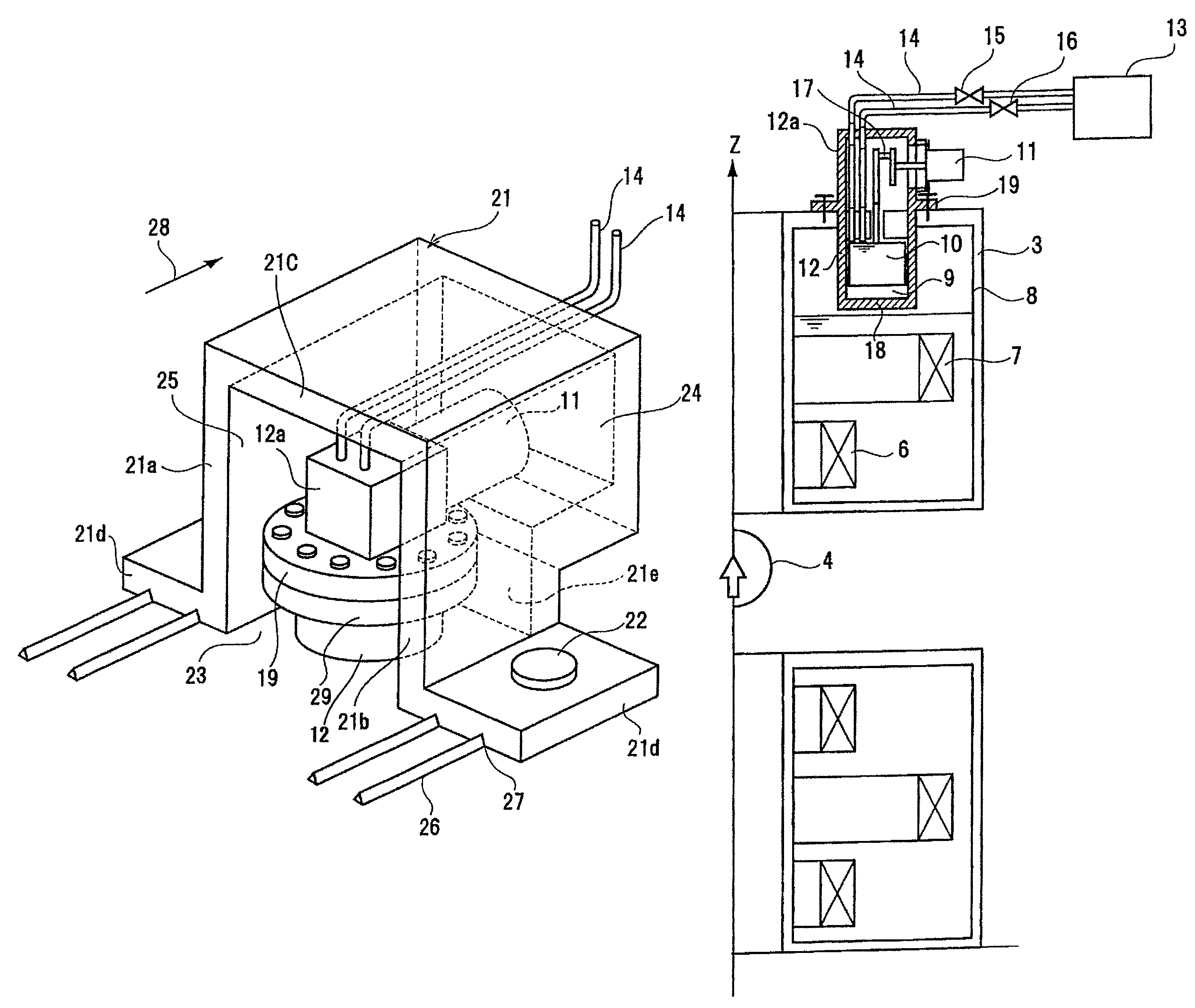
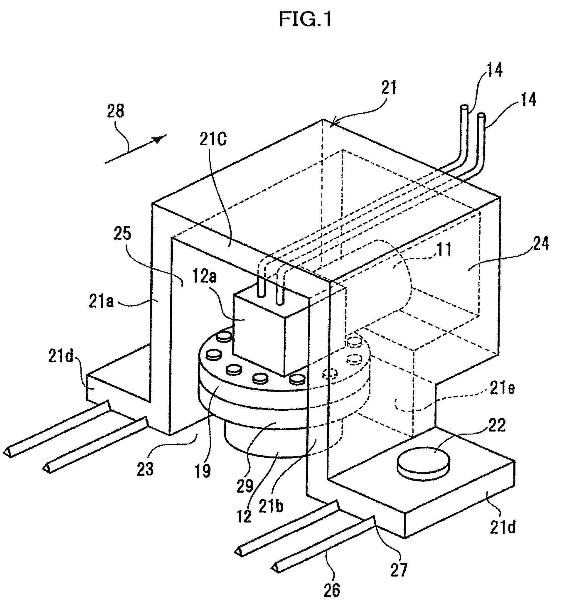
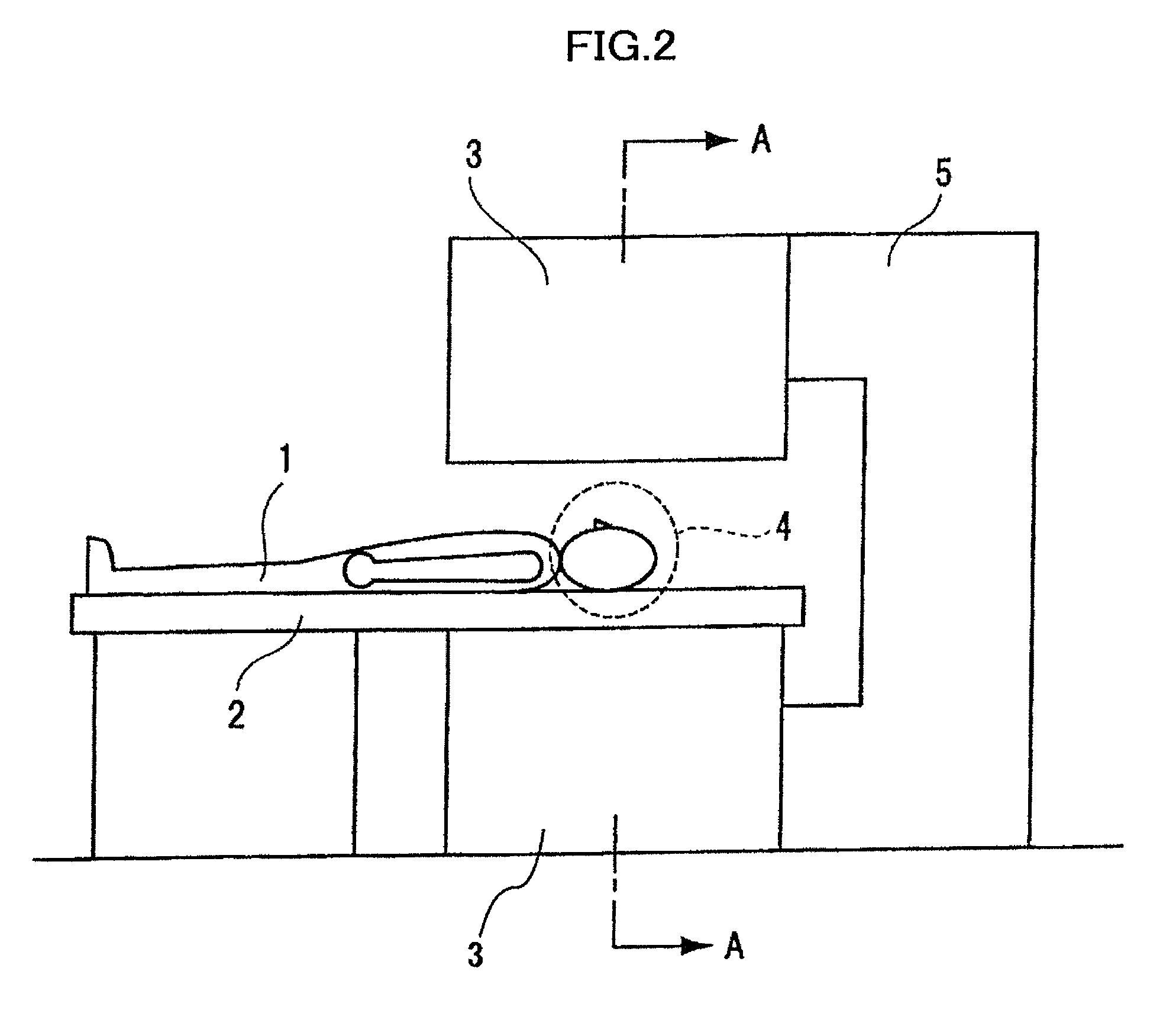
[0037]As shown in FIG. 2, a human subject 1 lies on a bed 2, and is traveled to a space sandwiched between a pair of vacuum vessels 3, which are opposing to each other above and below across the bed 2. Subsequently, a predetermined observation area 4 and an area for imaging tomographic planes of the human subject 1 are aligned so that the former includes the latter. A pair of the vacuum vessels 3 are connected by a support pillar 5. FIG. 3 is a cross sectional block diagram showing the main part of a cooling system of the MRI machine when cut along the line A-A in FIG. 2, and the bed 2 is not shown herein. Each vacuum vessel 3 houses a static magnetic field generating source, which generates a static magnetic field whose magnetic field is indicated with a direction of an arrow shown in FIG. 3, in the observation area 4. Each vacuum vessel 3 houses a primary coil 6; a superconducting shield coil 7 which flows therein an electrical current in a direction opposite that flowing in the p...

second embodiment

[0058]FIG. 9 is a perspective view showing a magnetic shield structure according to a second embodiment of the present invention. The second embodiment has the same configuration as that of the first embodiment shown in FIG. 1, except that an opening space 25 of a magnetic shield 21 is shielded by a ferromagnetic material plate 21f, and that the magnetic shield 21 can be divided into two, taking a surface 31 connecting a pair of bolts 22 as a separation plane. Other than that, the same reference numerals are assigned to the same components as those in the first embodiment, and description thereof is omitted herefrom.

[0059]Similarly to the first embodiment shown in FIG. 1, the magnetic shield 21 in this embodiment has an opening space 23 surrounded by ferromagnetic material plates 21a,21b and ferromagnetic material plates 21e,21f, and extending in a reciprocating movement direction of a displacer 10. The opening space 23 is sufficiently longer in the reciprocating movement direction ...

third embodiment

[0062]FIG. 10 is a perspective view showing a magnetic shield structure according to a third embodiment of the present invention. The third embodiment has the same configuration as that of the first embodiment shown in FIG. 1, except that a thickness of a ferromagnetic material plate 21c is smaller than that of each of the ferromagnetic material plates 21a,21b. The ferromagnetic material plate 21c is placed between respective upper ends of the ferromagnetic material plates 21a,21b to cover an upper side of an opening space 23. Other than that, the same reference numerals are assigned to the same components as those in the first embodiment, and description thereof is omitted herefrom.

[0063]Even with the configuration described above, since magnetic field lines at the ferromagnetic material plate 21c direct vertically upward, each of two wider faces of the ferromagnetic material plate 21c is substantially vertical to the magnetic field lines. Thus, as described in “R. M. Bozorth, Ferr...


PUM

PropertyMeasurementUnit
static magnetic fieldaaaaaaaaaa
magnetic fieldaaaaaaaaaa
superconductingaaaaaaaaaa

Abstract

A superconducting electromagnet is provided with a magnetic shield for protecting, from a leakage magnetic flux of the superconducting electromagnet, a motor for driving a cryocooler for cooling a cooling medium in a coil vessel, in which the superconducting coil is housed with the cooling medium. The magnetic shield includes a pair of ferromagnetic material plates placed opposite each other across the motor. Leakage magnetic fluxes in an opening space formed between a pair of the ferromagnetic material plates are attracted thereto to drastically reduce a density of the leakage magnetic fluxes around the motor. The opening space formed between the ferromagnetic material plates also facilitates maintenance of the cryocooler and the motor.

Description

CROSS REFERENCE TO RELATED APPLICATIONS[0001]This application claims the benefit of Japanese Patent Application No. 2006-008665 filed on Jan. 17, 2006, the disclosure of which is incorporated herein by reference.BACKGROUND OF THE INVENTION[0002]1. Field of the Invention[0003]The present invention relates to a superconducting electromagnet, and more specifically, to a magnetic shield structure of a motor for driving a cryocooler provided for the superconducting electromagnet.[0004]2. Description of the Related Art[0005]A superconducting electromagnet is used, for example, in a magnetic resonance imaging (MRI) machine. The MRI machine measures a nuclear magnetic resonance (hereinafter referred to as an NMR) signal detected from an electromagnetic wave which is obtained according to a spin state of a hydrogen nucleus with the NMR phenomenon; processes the signal; and creates, from the processed signal, an image of a hydrogen nucleus density distribution in a human subject's body. When ...

Claims


Application Information

Patent Timeline
Patent Type & Authority Patents(United States)
IPC IPC(8): H01F1/00H01F6/00
CPCG01R33/3815G01R33/421H01F6/04F25B9/14F25B2500/06F25D19/00G01R33/3804H01F6/00H01F27/365H01F27/36H01F27/366
Inventor NAKAYAMA, TAKESHIMAENO, SHOGO
Owner HITACHI LTD
Why Eureka
Try Eureka