Boundary acoustic wave device

a acoustic wave and device technology, applied in piezoelectric/electrostrictive devices, device material selection, piezoelectric/electrostrictive devices, etc., can solve the problems of complex design of electrodes, increased cost of surface acoustic wave devices, and degraded resonant, etc., to achieve small power flow angle, small propagation loss, and large electromechanical coefficient

Active Publication Date: 2007-01-11
MURATA MFG CO LTD
View PDF6 Cites 23 Cited by
  • Summary
  • Abstract
  • Description
  • Claims
  • Application Information

AI Technical Summary

Benefits of technology

[0017] To overcome the problems described above, preferred embodiments of the present invention provide a boundary acoustic wave device using a Stoneley wave which has a sufficiently large electromechanical coefficient, small propagation loss, small power flow angle, and a small temperature coefficient of frequency, and which can be manufactured by a simple method.

Problems solved by technology

Since the package having a cavity portion as described above is used, the cost of the surface acoustic wave device is increased.
The loss caused by the propagation of a boundary acoustic wave, that is, the propagation loss, may degrade the insertion loss of a boundary acoustic wave filter or may also degrade the resonant resistance or the impedance ratio of a boundary acoustic wave resonator, the impedance ratio being a ratio between the impedance at a resonant frequency and that at an antiresonant frequency.
Hence, the design of the electrodes is complicated.
In addition, a loss caused by a deviation in the angle is likely to be generated.
With a resonator, when an oscillation circuit is formed, the above-described change in operating frequency caused by the temperature results in abnormal oscillation.
However, it is difficult to form a SiO2 film such that a boundary acoustic wave propagates, and the non-patent document 2 discloses no measurement results of a Stoneley wave after actually forming the SiO2 film.

Method used


Image

  • Boundary acoustic wave device
  • Boundary acoustic wave device
  • Boundary acoustic wave device

Examples


example 1

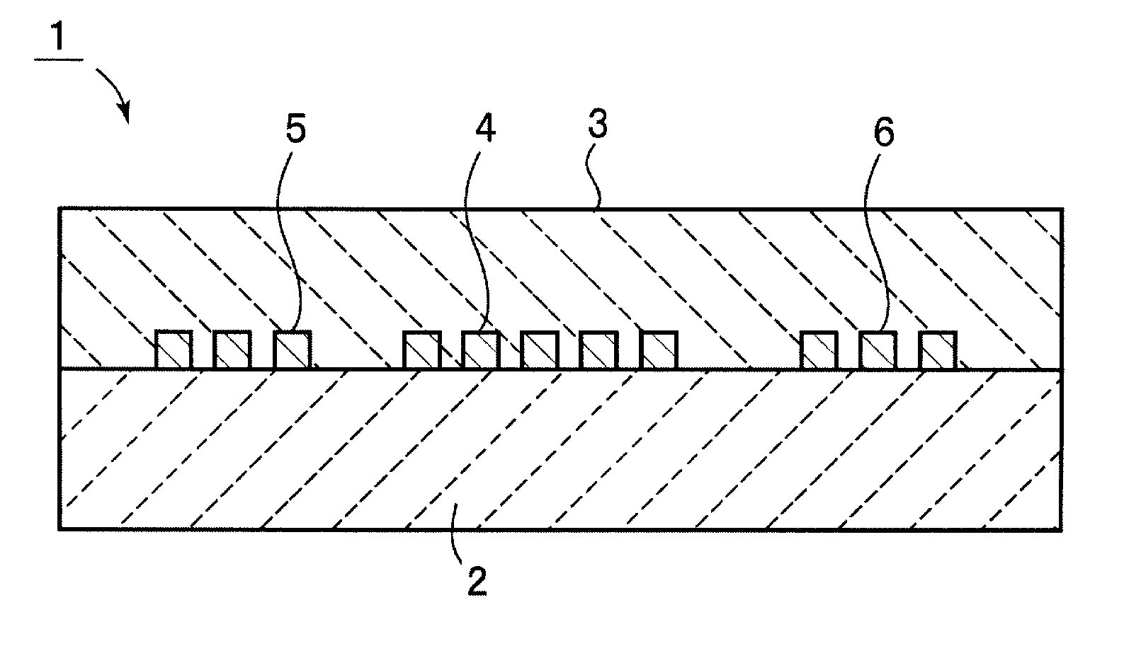
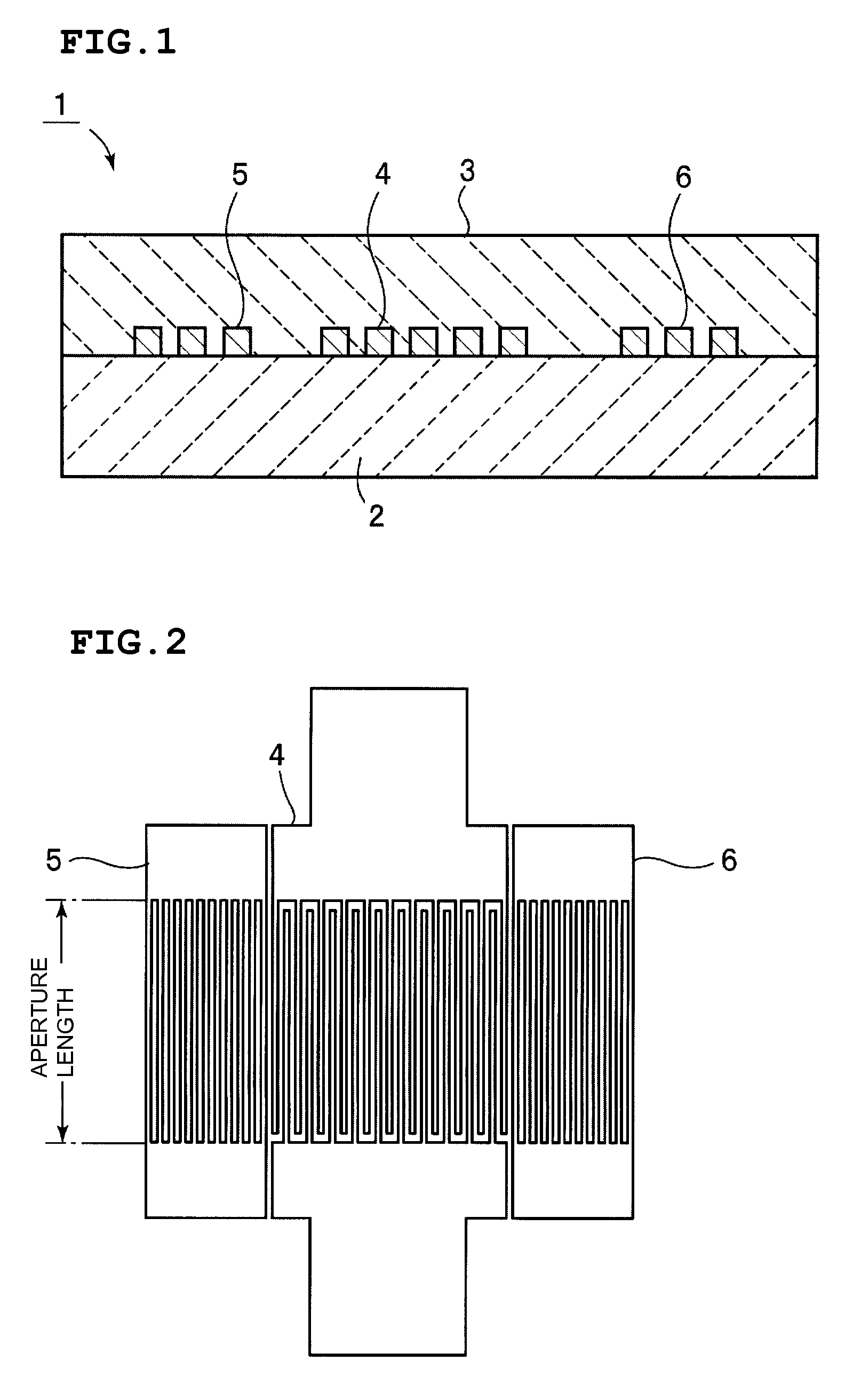
[0177] A 128° rotated Y plate X-propagation LiNbO3 substrate, that is, having Euler angles (0°, 38°, 0°) was prepared as the piezoelectric substance 2. On this LiNbO3 substrate, as an adhesion layer, a NiCr film was formed by an evaporation method. Next, on this adhesion layer, a Au film was formed by an evaporation method, followed by patterning using a lift-off method, such that the IDT 4 and the reflectors 5 and 6 were formed. In addition, a SiO2 film was formed by an RF magnetron sputtering method at a film-forming temperature of 200° C. so as to cover the IDT 4 and the reflectors 5 and 6.

[0178] The number of electrode finger pairs of the IDT 4 and the number of electrode fingers of each reflector were set to 50.5 and 51, respectively.

[0179] In addition, the crossing width of the electrode fingers of the IDT 4 was set to 30 λ. On the other hand, an aperture length A (see FIG. 2) of the reflectors 5 and 6 was set to 30.5 λ. In this example, λ was a placement period of the elect...

example 2

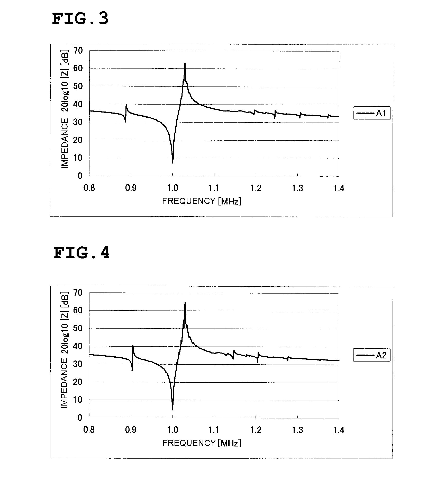
[0189] In Example 1, the spurious response was generated by the SH type boundary acoustic wave at a lower frequency side than that of the response by the Stoneley wave. In Example 2, this spurious response was intended to be suppressed.

[0190] That is, in order to suppress the spurious response by the SH boundary acoustic wave, the relationships of the Euler angle of a LiNbO3 substrate with the acoustic velocity V, the electromechanical coefficient k2, the propagation loss α, the temperature coefficient of frequency TCF, and the power flow angle (PFA) of the Stoneley wave and the SH type boundary acoustic wave were obtained. The calculation was performed based on a method disclosed in “A Method For Estimating Optimal Cuts and Propagation Directions for Excitation and Propagation Directions for Excitation of Piezoelectric Surface Waves” (J. J. Campbell and W. R. Jones, IEEE Trans. Sonics and Ultrasonics, Vol. SU-15, No. 4 (October 1968) pp. 209 to 217). In the case of a free boundary...

example 3

[0204] A 120° rotated Y plate X-propagation LiNbO3 substrate, that is, having Euler angles (0°, 30°, 0°), was prepared as the piezoelectric substance 2 using the calculation method described in Example 2, and taking into account easy thin film formation and a function of counteracting the TCF of LiNbO3, a SiO2 film was selected as the dielectric substance 3. By forming electrodes using electrode materials having various densities, boundary acoustic wave devices were formed. Subsequently, the relationships of the electrode thickness of each of the boundary acoustic wave devices thus formed with the acoustic velocity, the propagation loss α (dB / λ), the electromechanical coefficient k2 (%), and the temperature coefficient of frequency TCF of the Stoneley wave were obtained. The results are shown in FIGS. 70 to 116. It is noted that the power flow angle PFA was zero under all the conditions.

[0205] In the 120° rotated Y plate X-propagation LiNbO3 substrate, the acoustic velocity of a lo...


PUM


Abstract

A dielectric substance is laminated on one surface of a piezoelectric substance, and an IDT and reflectors are disposed as electrodes at a boundary between the piezoelectric substance and the dielectric substance, and the thickness of the electrodes is determined so that the acoustic velocity of the Stoneley wave is decreased less than that of a slow transverse wave propagating through the dielectric substance and that of a slow transverse wave propagating through the piezoelectric substance, thereby forming a boundary acoustic wave device.

Description

BACKGROUND OF THE INVENTION [0001] 1. Field of the Invention [0002] The present invention relates to a boundary acoustic wave device using a Stoneley wave, and more particularly, to a boundary acoustic wave device using a Stoneley wave and including electrodes that are disposed at a boundary between a piezoelectric substance and a dielectric substance. [0003] 2. Description of the Related Art [0004] Heretofore, various surface acoustic wave devices have been used for RF and IF filters in mobile phones, resonators in VCOs, VIF filters in televisions, and other devices. Surface acoustic wave devices use a surface acoustic wave, such as a Rayleigh wave or a first leaky wave, which propagates along a surface of a medium. [0005] Since the acoustic wave propagating along a surface of a medium, a surface acoustic wave is sensitive to changes in the surface condition of the medium. Accordingly, in order to protect a surface of a medium along which a surface acoustic wave propagates, a surfa...

Claims


Application Information

Patent Timeline
Patent Type & Authority Applications(United States)
IPC IPC(8): H03H9/125H01L41/09H01L41/18H03H9/02H03H9/13H03H9/145H03H9/25
CPCH03H9/0222
Inventor KANDO, HAJIME
Owner MURATA MFG CO LTD
Why Eureka
Try Eureka