Piezoelectric resonator, method for adjusting frequency thereof and communication apparatus comprising said resonator

A piezoelectric resonator and resonant frequency technology, applied in piezoelectric devices/electrostrictive devices, piezoelectric/electrostrictive/magnetostrictive devices, circuits, etc., can solve difficult applications, automation difficulties, performance changes, etc. question

Inactive Publication Date: 2003-08-13
MURATA MFG CO LTD
View PDF5 Cites 0 Cited by
  • Summary
  • Abstract
  • Description
  • Claims
  • Application Information

AI Technical Summary

Problems solved by technology

In this case, automation would be difficult and would result in variations in performance beyond resonant and anti-resonant frequencies
Therefore, this method is practically difficult to apply

Method used


Image

  • Piezoelectric resonator, method for adjusting frequency thereof and communication apparatus comprising said resonator
  • Piezoelectric resonator, method for adjusting frequency thereof and communication apparatus comprising said resonator
  • Piezoelectric resonator, method for adjusting frequency thereof and communication apparatus comprising said resonator

Examples


Embodiment Construction

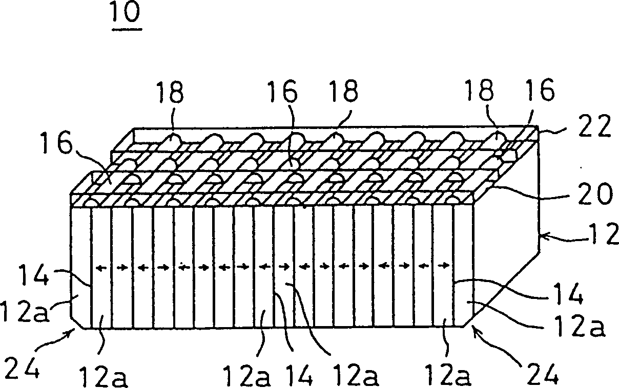
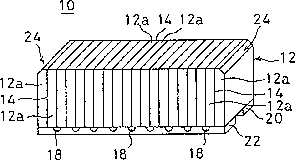
[0047] See figure 1 with figure 2 The piezoelectric resonator 10 includes, for example, a base body 12 in the form of a substantially rectangular block. The base 12 includes, for example, about 20 laminated piezoelectric material layers 12a made of piezoelectric ceramics. These piezoelectric material layers 12a are formed into a uniform size. These piezoelectric material layers 12a are polarized along the longitudinal direction of the base body 12, so that the polarization directions of each pair of adjacent piezoelectric material layers 12a are opposite to each other, such as figure 1 As shown by the arrow in. However, at the opposite end, the piezoelectric material layer 12a is preferably not polarized. In addition, at the opposite end, the piezoelectric material layer 12a may also be polarized.

[0048] The internal electrode 14 is provided between the piezoelectric layers 12 a of the base body 12. Therefore, the internal electrodes are arranged to be substantially perpendic...


PUM


Abstract

A base member of a piezoelectric resonator includes a laminated body having a plurality of piezoelectric layers which are alternately polarized in opposite directions along the longitudinal direction of the base member and inner electrodes provided between the piezoelectric layers. On a first side surface of the base member, each of two external electrodes is arranged so as to be connected to one of two groups of alternate inner electrodes. Cut portions for adjusting a frequency of the piezoelectric resonator to a higher frequency are respectively formed at edge portions of the base member at opposite ends in the longitudinal direction of a second side surface opposite from the first side surface of the base member.

Description

Technical field [0001] The present invention relates to a piezoelectric resonator, a method for adjusting the frequency of the piezoelectric resonator, and a communication device containing the piezoelectric resonator. The present invention particularly relates to piezoelectric resonators applied to electronic components such as vibrators, discriminators, or filters. Background technique [0002] In a conventional piezoelectric resonator, external electrodes are respectively provided on the two main surfaces of a piezoelectric substrate, which adopts a rectangular or square plate shape. The piezoelectric substrate is polarized along its thickness direction, and by inputting a signal between the electrodes, an electric field is applied along the thickness direction of the piezoelectric substrate to make the piezoelectric substrate vibrate in a direction parallel to its main surface. [0003] The piezoelectric resonator is of a non-hardened type, in which the electric field directi...

Claims


Application Information

Patent Timeline
IPC IPC(8): H01L41/08H01L41/083H03HH03H3/04H03H9/00H03H9/02H03H9/10H03H9/15H03H9/17H03H9/205H03H9/58H04B1/26
CPCH03H3/04H03H9/1014H03H9/178H03H9/13H03H9/125H03H9/54H03H9/171
Inventor 川合丰山崎武志
Owner MURATA MFG CO LTD
Why Eureka
Try Eureka